
Bearing wear in an F6A
Introduction
The Suzuki F6A is a high-reving three cylinder engine with 4 main bearings. This article investigates the bearing system, oiling distribution through the rotating assembly and wear on a set of bearings removed from a used F6A.
The Bearing System
The F6A crankshaft has three crank throws and four main bearings. The mains are numbered 1 through 4 from the timing end of the engine to the flywheel end of the engine.
As is common for Japanese engines from this time period, main bearings are nominally 2 mm thick and rod bearings are nominally 1.5 mm thick. For both bearing types the top and bottom shell are identical. Mains, therefore, have 360 degree oiling.
The OEM bearings are manufactured by Taiho. They are of a bimetal construction, steel backing with an aluminum alloy face. According to this article from Engine Builder Magazine the popularity of bimetal bearings in OEM applications has to do with its long service life for light load applications, but is not ideal for heavy loads.
The F6A has a single pair of thrust bearings mounted on the block side of the #3 main. It is more ideal to have a 360 degree thrust bearing configuration, such as the Toyota 4A-G has. Even so, Engines such as the Mazda BP have proven to be reliable with a similar 180 degree configuration.
The Oiling System
To provide oiling, the F6A has passages drilled through the crankshaft from the mains to the crankpins. These are manufactured as individual holes from a main to a crankpin. This style is shown as A in the figure below. This figure was originally published by Richard white on the club4ag FAQ and tech pages.
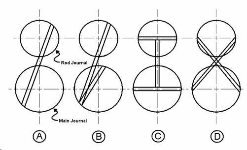
High-performance engines, such as the before-mentioned 4A-G or the venerable Suzuki Hayabusa engine, have cross drinlled crankshafts, like C in the above figure. A cross-drilled 4A-G crankshaft is shown in the figure below.
Balance
Like all inline three cylinder four stroke engines, the F6A has some balancing issues. In the case of the F6A these difficulties create some interesting symptoms for the engine bearings.
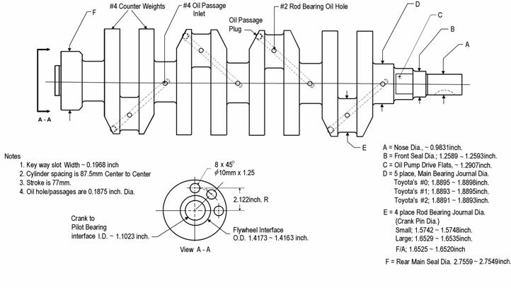
To help counteract these balance issues the F6A crankshaft has 4 counter weights, around crankpins 1 and 3. They’re 180 degrees out of phase from each other, and 90 degrees out of phase with the second crankpin.
Worn bearings
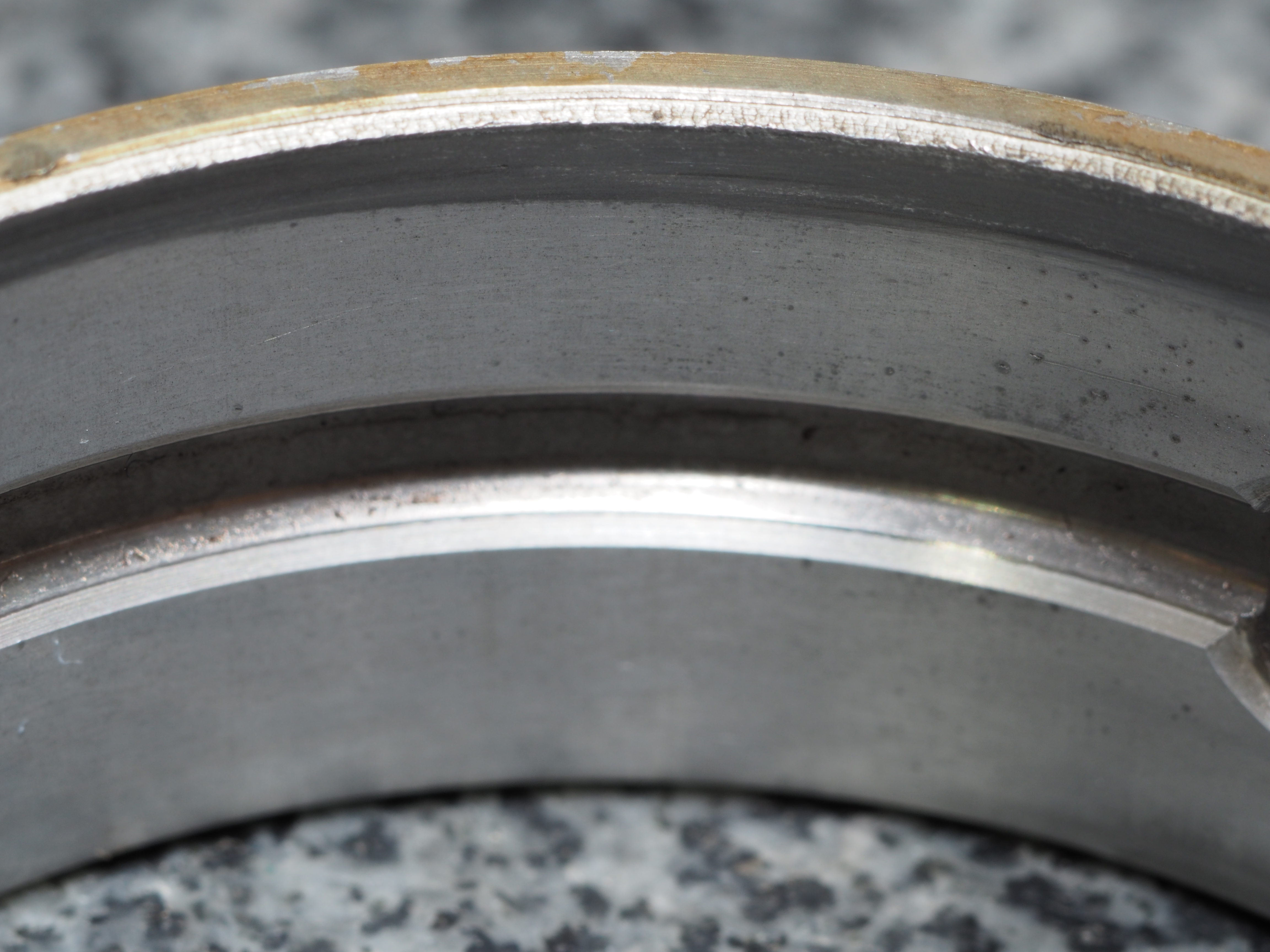
The above picture shows a main bearing shell removed from an F6A from an EA11R. This bearing shows some interesting signs of wear. The main body of the bearing shows some embedded particles. An advantage of aluminum bearings, as discussed in the Engine Builder Magazine cited earlier, is the ability to embed particles, minimizing their effect on the bearing’s performance. This isn’t unusual for a high-mileage bimetal bearing.
What is unusual is the heavily-worn edge of the bearing. Mains number one and four showed this wear on both bearing shells. The wear pattern was toward the timing belt side for the first main and toward the flywheel side for the fourth main. The wear is equal in width around the entire circumfrence of the bearing. The crankshaft showed taper matching the wear on the bearings. This shows that the crankshaft was precessing around its axis of rotation, an effect of the inherent imbalance in the engine.
Mitigation
Power LLC sells coated trimetal bearings in discrete size ranges, which is advantageous for producing consistent and precise bearing clearances. Power LLC bearings are based on Daido parts. Unfortunately, main bearings are currently discontinued due to a lack of available parts from Daido.
Conclusion
The Suzuki F6A has some interesting challenges when it comes to the reliability of the rotating assembly. Building power is the product of many decisions balancing performance, reliability, delivery, and cost. Decades of performance have shown that these challenges don’t preclude the F6A from producing power.