<?xml version="1.0" encoding="utf-8"?><feed xmlns="http://www.w3.org/2005/Atom" ><generator uri="https://jekyllrb.com/" version="4.3.4">Jekyll</generator><link href="https://www.keisport.us/feed.xml" rel="self" type="application/atom+xml" /><link href="https://www.keisport.us/" rel="alternate" type="text/html" /><updated>2024-11-11T11:49:49-06:00</updated><id>https://www.keisport.us/feed.xml</id><title type="html">Kei Sport USA</title><subtitle>Dedicated to building and maintaining performance Kei cars including the Autozam AZ-1, Honda Beat, and Suzuki Cappuccino.</subtitle><author><name>GitHub User</name><email>your-email@domain.com</email></author><entry><title type="html">Development Cadence</title><link href="https://www.keisport.us/2024/11/11/cadence.html" rel="alternate" type="text/html" title="Development Cadence" /><published>2024-11-11T00:00:00-06:00</published><updated>2024-11-11T00:00:00-06:00</updated><id>https://www.keisport.us/2024/11/11/cadence</id><content type="html" xml:base="https://www.keisport.us/2024/11/11/cadence.html"><![CDATA[<h2 id="news">News</h2>

<p>We’re switching to a scheduled cadence for producing and shipping PNPs. We’ll be doing a batch around December/January and a batch around June/July.
If you’re on our wait list right now, I think we’ll have you taken care of in this upcoming batch.</p>

<p>I don’t expect we’ll be taking on any more engine work, but feel free to <a href="/contact">reach out</a> if you have an interesting idea.</p>

<p>We do still have some Cusco Cappuccino LSDs. <a href="/contact">Contact us</a> if you want one. $650 shipped in the US.</p>

<h2 id="reasoning">Reasoning</h2>

<p>If you’re reading this news here, I feel like you’re interested in more information than we shared on social media. Kei Sport has a single permanent employee. Me. Jeff Burdick. I bring in people when necessary to help with some aspects of operation, research, and development, but primarily Kei Sport is a personal project.</p>

<p>I recently started a graduate degree. It’s going well and I want to take it as far as I can. This requires a significant amount of time, attention, and energy. I do not feel I can provide Kei Sport USA with the attention I think it requires.</p>

<h2 id="conclusion">Conclusion</h2>

<p><a href="/contact">contact us</a> if you would like to talk about your Kei Sport.</p>]]></content><author><name>Jeffrey P Burdick</name></author><summary type="html"><![CDATA[We'll be shipping PNPs January and July]]></summary></entry><entry><title type="html">Switched on Throttle</title><link href="https://www.keisport.us/2024/04/21/EA11R-PNP-v1-5.html" rel="alternate" type="text/html" title="Switched on Throttle" /><published>2024-04-21T00:00:00-05:00</published><updated>2024-04-21T00:00:00-05:00</updated><id>https://www.keisport.us/2024/04/21/EA11R-PNP-v1-5</id><content type="html" xml:base="https://www.keisport.us/2024/04/21/EA11R-PNP-v1-5.html"><![CDATA[<h2 id="introduction">Introduction</h2>

<p>We’ve added some new features for Our EA11R Cappuccino PNP, including variable throttle position sensor (TPS) support and an additional digital output for the Vaccum Switching Valve (VSV).</p>

<h2 id="throttle-position-sensor">Throttle Position Sensor</h2>

<p>The engine management system needs to know where the throttle is to conduct certain functions, such as enabling closed-loop idle, deceleration fuel cut, and acceleration enrichment.</p>

<h3 id="throttle-switches">Throttle Switches</h3>

<p>The EA11R Cappuccino uses a series of switches for determining the position of the throttle. This was relatively common for Japanese cars at that time. The NA6 Miata used throttle switches, for example. These switches sense when the throttle is completely closed and when the throttle is completely open, but doesn’t otherwise communicate the state of the state of the throttle.</p>

<h3 id="variable-throttle-position-sensor">Variable Throttle Position Sensor</h3>

<p>More modern systems incorporate a variable throttle position sensor. This communicates the position of the throttle continuously from fully closed to fully open. The engine management system uses this to sense fast changes in throttle position, which it can use to add and subtract fuel quickly, allowing for faster throttle response.</p>

<h3 id="pnp-functionality">PNP functionality</h3>

<p>Our PNP includes circuitry which interprets these throttle switches and outputs a signal which the microsquirt can read. This works surprisingly well in this application, even with large injectors. Even so, incorporating the ability to read a a variable TPS isn’t particularly difficult, so we included it in this board revision.</p>

<h3 id="variable-tps-mode">Variable TPS mode</h3>

<p>A reference voltage is sent out on the IDL pin and the return TPS value is read on the WOT pin. The third pin of the throttle switches circuit is a ground reference at the ECU. These are the three connections required for a variable TPS.</p>

<p>To enable the variable TPS functionality, a series of solder jumpers must be opened on the PCB and a solder connection formed on the PCB. This will be added to the PNP manual before PNPs ship. If requested, KeiSport USA can ship a PNP in this mode. A variable TPS needs to be installed and wired in place of the throttle switches. The output of the variable TPS should be verified in TunerStudio and closed throttle and wide-open-throttle limits should be set.</p>

<h3 id="tuning">Tuning</h3>

<p>The acceleration enrichment settings for this tune are based on the response of the throttle switches. These will need to be retuned for the TPS.</p>

<h2 id="vacuum-switching-valve">Vacuum Switching Valve</h2>

<p>The OEM ECU uses a VSV to control vacuum to the stock air bypass valve. We’ve included circuitry to drive this VSV and programmed it to respond appropriately. This can be repurposed for other uses, if desired.</p>

<h2 id="conclusion">Conclusion</h2>

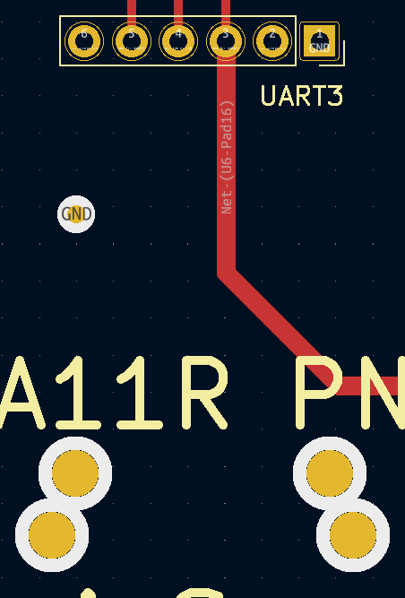
<p>It’s worth mentioning that there’s quite a more IO available on our PNP than this, including positions for an arduino, two CAN Bus circuits, and three UART circuits.</p>

<p><a href="/contact">contact us</a> if you would like to order a plug-and-play!</p>]]></content><author><name>Jeffrey P Burdick</name></author><summary type="html"><![CDATA[Improvements for our EA11R PNP V1.5]]></summary></entry><entry><title type="html">Big injectors for the EA11R PNP</title><link href="https://www.keisport.us/2022/12/20/EA11R-PNP-bigInjectors.html" rel="alternate" type="text/html" title="Big injectors for the EA11R PNP" /><published>2022-12-20T00:00:00-06:00</published><updated>2022-12-20T00:00:00-06:00</updated><id>https://www.keisport.us/2022/12/20/EA11R-PNP-bigInjectors</id><content type="html" xml:base="https://www.keisport.us/2022/12/20/EA11R-PNP-bigInjectors.html"><![CDATA[<h2 id="introduction">Introduction</h2>

<p>Our inital PNP tune was built for the OEM Suzuki injectors and manifold pressures above 210 kPa. We went through some rather elaborate steps to make it as appropriate as possible for further expansion. Nonetheless, we have gotten quite a few requests for a tune similar to an Suzuki or Monster Sport N2 ECU; which would be appropriate for larger injectors and manifold pressures above 210 kPa.</p>

<h2 id="whats-necessary-for-changing-injectors">What’s necessary for changing injectors</h2>

<p><img src="/assets/blog/2022-12-20/responseCurve.png" alt="" /></p>

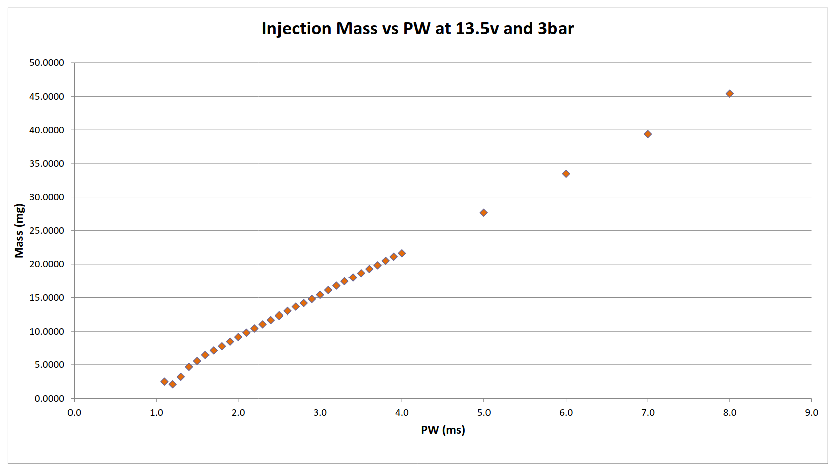
<p>Injectors do not behave linearly. The relationship between the applied pulse width and the mass of fuel delivered is different for every injector. This must either be compensated for, or the nonlinearity ends up being baked into the VE tables. If injectors are changed, then there is a discrepency between the commanded lambda and logged.</p>

<p>There are a few parameters in the engine management system to compensate for these differences. Some of these are better than others. Likewise, some injectors behave better than others. Many tuners do not bother with these changes, as it is time consuming. They allow the nonlinearity to be baked into the VE tables. This is less than ideal, but isn’t the top priority for tuners.</p>

<h2 id="whats-difficult-about-the-ea11r">What’s difficult about the EA11R</h2>

<p>There are a few things which make the EA11R more difficult than most. The fuel system operates at 2.2 BAR. This lower pressure helps with small pulse widths. Most fuel systems, and therefore most injector response data, operates at 3 BAR or higher. The Microsquirt Module in the EA11R PNP doesn’t have the best compensation system. Some small amount of nonlinearity ends up in the VE tables. Because there are only 3 injectors available for the system, they end up being rather large for the amount of power being produced, and idle pulsewidths end up VERY short. This is where injectors behave the worst.</p>

<p>A bigger problem is that there seems to be a rather large difference from one DOHC F6A to another. More than the difference in history, any individual owner has different intentions, they’ll have put different parts together. I don’t think we’ve gotten two customers who want to use the same model of injectors.</p>

<p>An F6A needs to be particularly healthy to behave above 1.1 BAR of boost for very long. The OEM head gasket becomes a problem. The cooling system becomes a problem. The cooling system problems cause head gasket problems. So turning up the boost first requires quite a lot of preventative maintenance and even replacing the head gasket.</p>

<h2 id="what-weve-provided">What we’ve provided</h2>

<p>We’ve decided that the best course of action would be to pick a set of appropriate injectors and perform the necessary tuning to make them behave with the EA11R fuel system and PNP.After a lot of review, we settled on <a href="https://deatschwerks.com/products/22s-00-0450-4">Deatschwerks 22S-00-0450-4 450 cc injectors</a>. These are current production injectors, available globally, which are plug-and-play for the DOHC F6A. We can include them with a PNP purchase for 360 USD.</p>

<p>This is still not a complete solution, as differences in turbochargers, manifolds, intercoolers, exhuasts, etc. will all change the performance of the overall vehicle, it does provide the next step from our base tune toward more boost. It’s not as polished as our base tune, but it runs, drives, cold-starts, and behaves. All of our tunes will be improved as we receive datalogs back from customers and testers and we’ll be sharing what we learn here.</p>

<p>Current tunes are available in our <a href="https://gitlab.com/keisport/ea11r-microsquirt-pnp/">git respository</a>. More information on interacting with the tunes can be found in <a href="https://www.keisport.us/pnp/tune">our documentation</a>.</p>

<h2 id="conclusion">Conclusion</h2>

<p><a href="/contact">contact us</a> if you would like to order a plug-and-play!</p>]]></content><author><name>Jeffrey P Burdick</name></author><summary type="html"><![CDATA[We have released a base tune for big injectors; here's more on what to expect]]></summary></entry><entry><title type="html">EA11R PNP V1.2</title><link href="https://www.keisport.us/2022/12/01/EA11R-PNP-V1.2.html" rel="alternate" type="text/html" title="EA11R PNP V1.2" /><published>2022-12-01T00:00:00-06:00</published><updated>2022-12-01T00:00:00-06:00</updated><id>https://www.keisport.us/2022/12/01/EA11R-PNP-V1.2</id><content type="html" xml:base="https://www.keisport.us/2022/12/01/EA11R-PNP-V1.2.html"><![CDATA[<h2 id="introduction">Introduction</h2>

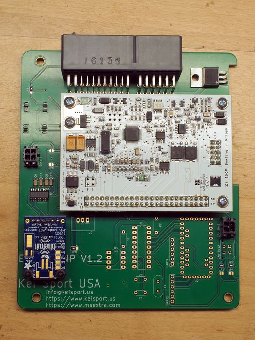
<p>We have started assembly and testing of V1.2 of our EA11R Cappuccino PNP. In this post we’ll discuss new features and differences for the V1.2 board.</p>

<p><img src="/assets/pnp/PNPv1.2.jpg" alt="" /></p>

<h2 id="changes">Changes</h2>

<p>All DIP switches have been replaced with solder bridges. Changing jumper settings will require soldering or desoldering these bridges.</p>

<p><img src="/assets/blog/2022-12-01/solderBridges.png" alt="" /></p>

<p>The provisions for the <a href="https://www.arduino.cc/en/Main/ArduinoBoardProMini">Arduino Pro Mini</a> or <a href="https://learn.sparkfun.com/tutorials/ast-can485-hookup-guide">SparkFun AST-CAN485 Dev Board</a> and its associated <a href="https://en.wikipedia.org/wiki/CAN_bus">CAN Bus</a> and <a href="https://en.wikipedia.org/wiki/Universal_asynchronous_receiver-transmitter">UART</a> hardware has been switched to <a href="https://en.wikipedia.org/wiki/Through-hole_technology">through hole construction</a>.</p>

<p>By using through hole construction the Arduino, CAN Bus, and UART hardware can be assembled as necessary. This reduces lead times for construction and testing.</p>

<h2 id="new-features">New Features</h2>

<p>V1.2 PNPs are now provisioned for more robust UART module connections. This means that <a href="https://en.wikipedia.org/wiki/USB">USB</a> and <a href="https://en.wikipedia.org/wiki/Bluetooth">Bluetooth</a> modules can be installed permanently in the PNP. The ECU can now be connected to phones, tablets, computers, or head units via USB or Bluetooth without external hardware!</p>

<p><img src="/assets/blog/2022-12-01/UARTmodule.png" alt="" /></p>

<p>The following UART modules can be installed permanently in the PNP:</p>

<p><img src="/assets/blog/2022-12-01/USBmodule.jpg" alt="" /></p>
<ul>
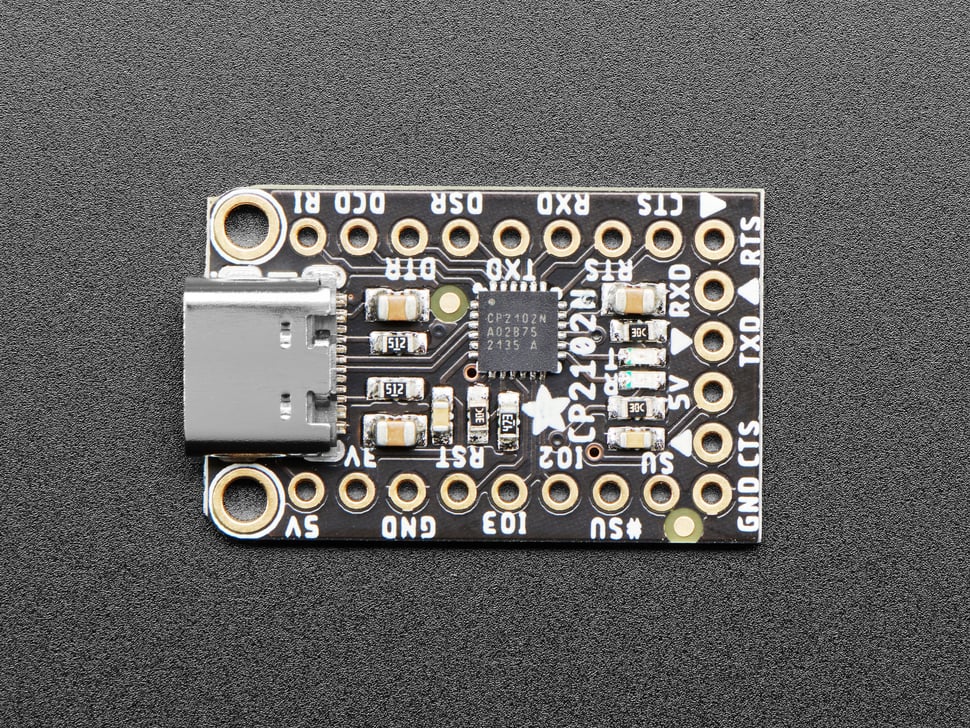
  <li><a href="https://www.adafruit.com/product/5335">Adafruit CP2102N Friend - USB to Serial Converter</a></li>
</ul>

<p><img src="/assets/blog/2022-12-01/bluetoothModule.jpg" alt="" /></p>
<ul>
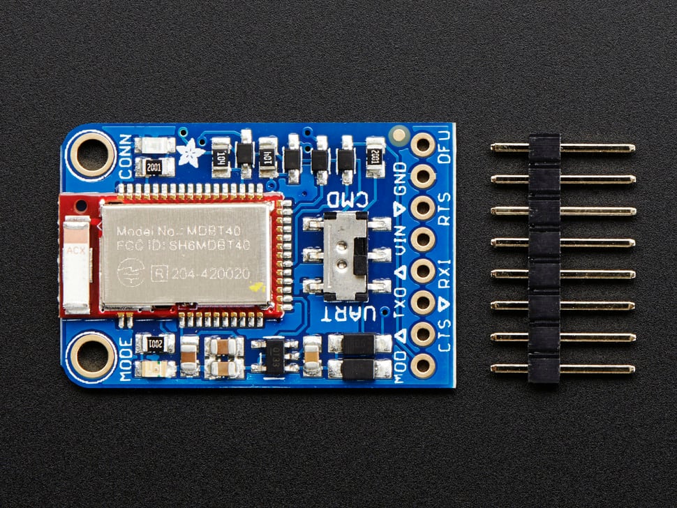
  <li><a href="https://www.adafruit.com/product/2479">Adafruit Bluefruit LE UART Friend</a></li>
</ul>

<h2 id="conclusion">Conclusion</h2>

<p><a href="/contact">contact us</a> if you would like to order a plug-and-play!</p>]]></content><author><name>Jeffrey P Burdick</name></author><summary type="html"><![CDATA[Updates and changes to the EA11R PNP for V1.2]]></summary></entry><entry><title type="html">IHI RHB31 VS Hitachi HT07-4A</title><link href="https://www.keisport.us/2022/03/25/RHB31vsHT07-4A.html" rel="alternate" type="text/html" title="IHI RHB31 VS Hitachi HT07-4A" /><published>2022-03-25T00:00:00-05:00</published><updated>2022-03-25T00:00:00-05:00</updated><id>https://www.keisport.us/2022/03/25/RHB31vsHT07-4A</id><content type="html" xml:base="https://www.keisport.us/2022/03/25/RHB31vsHT07-4A.html"><![CDATA[<h2 id="introduction">Introduction</h2>

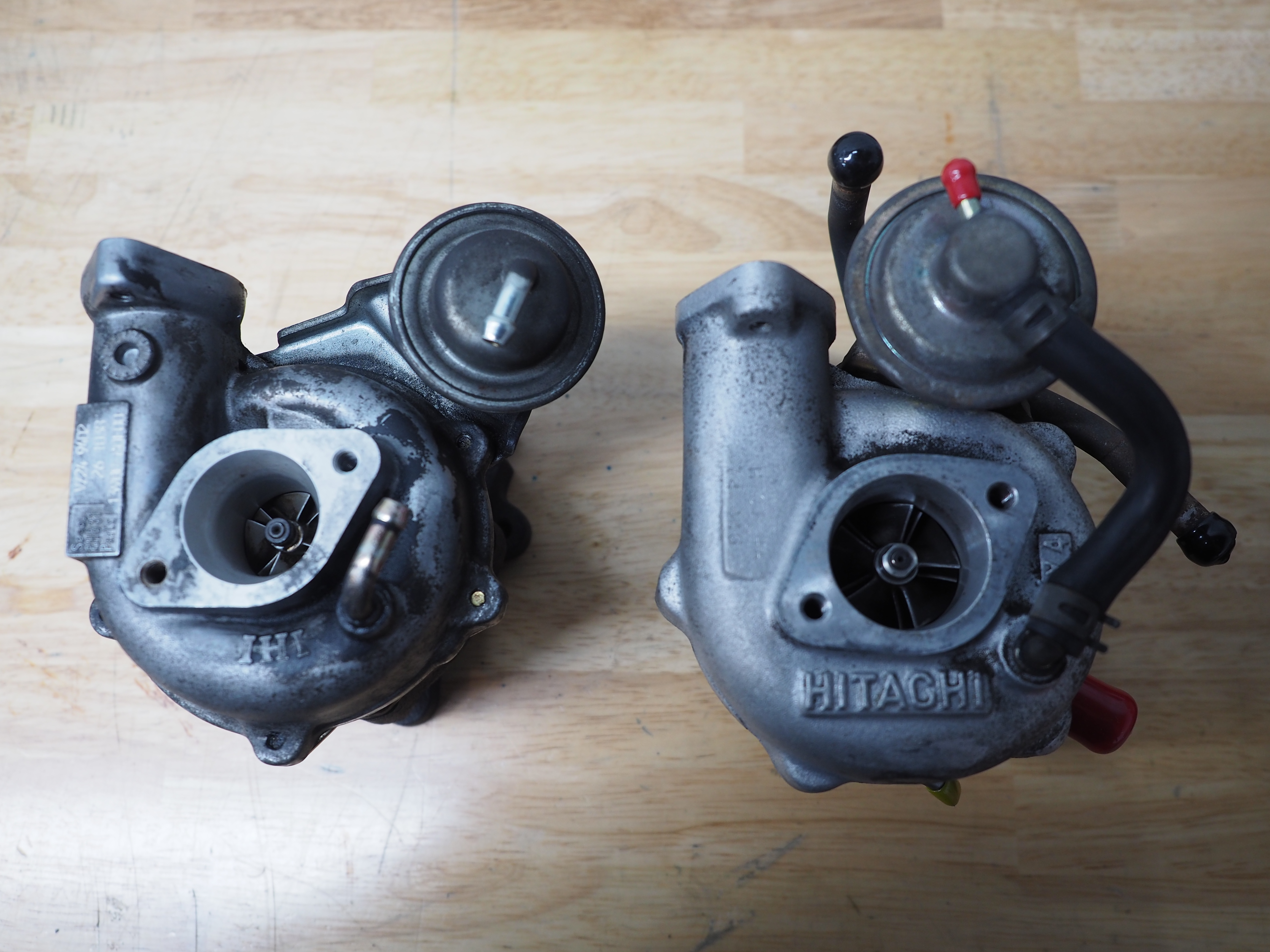
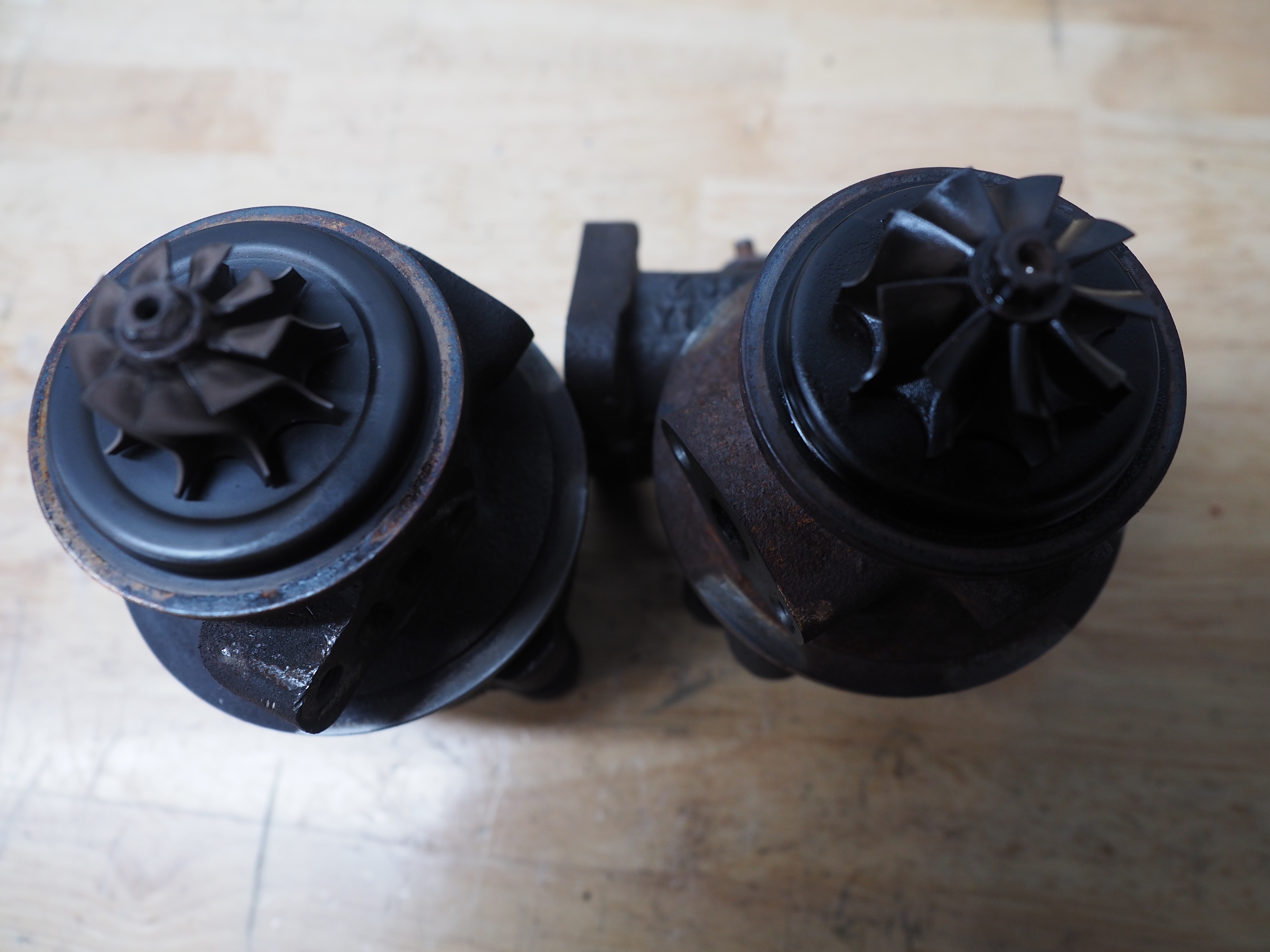
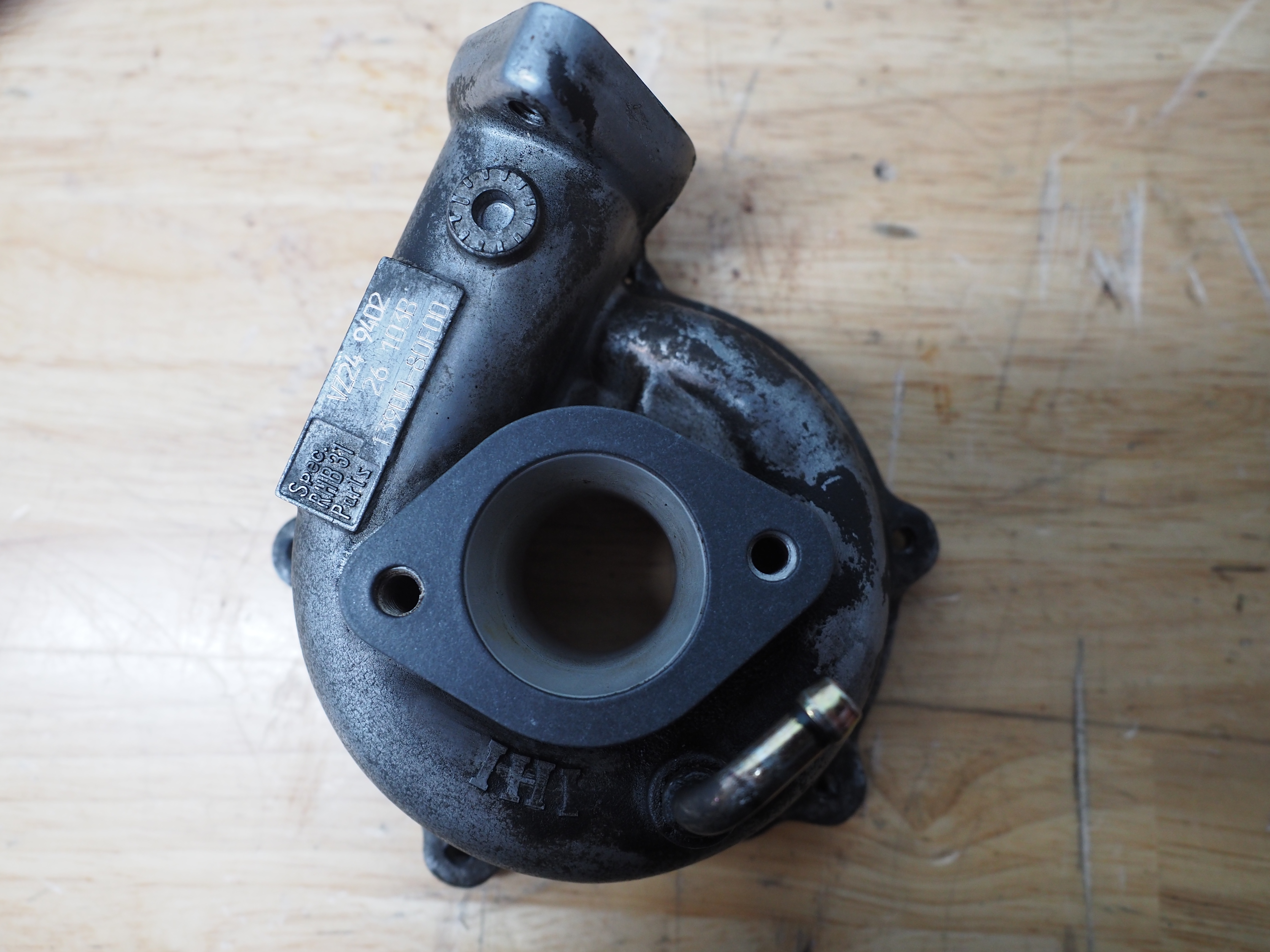
<p>The IHI RHB31 VZ24 9402 is the OEM turbocharger on the Suzuki F6A DOHC and K6A. A popular upgrade is the Hitachi HT07-4A. The following picture is pretty popular on the internet, but usually the comparisons stop there.</p>

<p><img src="/assets/blog/2022-03-25/JPB11243.JPG" alt="" /></p>

<p>Here we explore the differences and similarities between the two turbochargers in more detail.</p>

<h2 id="compressor-wheel">Compressor wheel</h2>

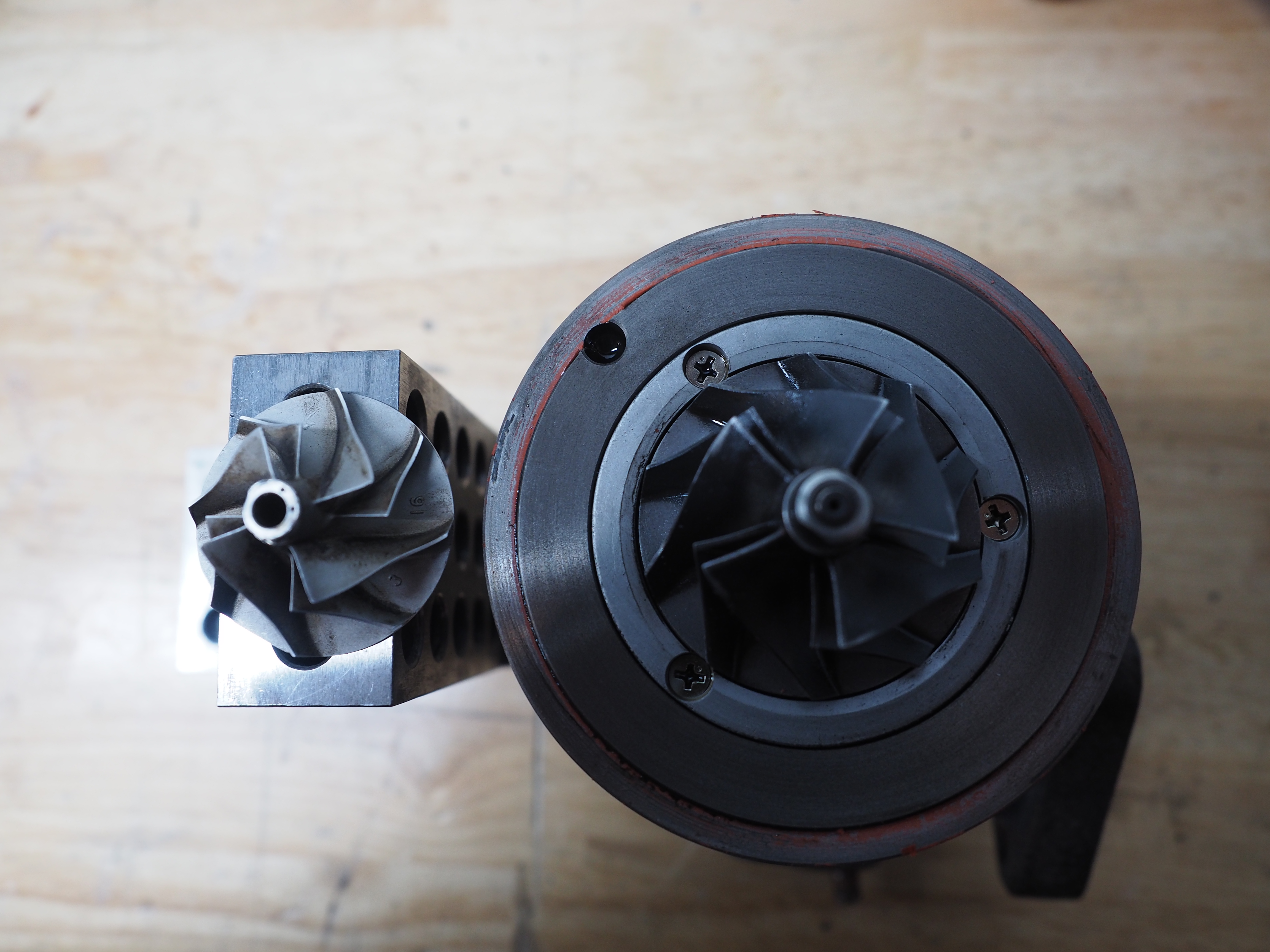
<p>On the left is the compressor wheel for the IHI RHB31 VZ24. On the right is the Hitachi HT07-4A. The IHI RHB31 VZ24 has 4 full-height blades and 4 reduced-height blades. The Hitachi HT07-4A has 5 full-height blades and 5 reduced-height blades.</p>

<p><img src="/assets/blog/2022-03-25/JPB11248.JPG" alt="" /></p>

<p>The following table shows the dimensional differences between the compressor wheel for the IHI RHB31 VZ24, the RHB31FW used in the Suzuki/Monster sport F100 kit, and the Hitachi HT07-4A.</p>

<table>
  <thead>
    <tr>
      <th>compressor</th>
      <th style="text-align: right">IHI RHB31 VZ24</th>
      <th style="text-align: right">IHI RHB31FW</th>
      <th style="text-align: right">Hitachi HT07-4A</th>
    </tr>
  </thead>
  <tbody>
    <tr>
      <td>major diameter</td>
      <td style="text-align: right">36</td>
      <td style="text-align: right">40</td>
      <td style="text-align: right">46</td>
    </tr>
    <tr>
      <td>minor diameter</td>
      <td style="text-align: right">25</td>
      <td style="text-align: right">30</td>
      <td style="text-align: right">30</td>
    </tr>
    <tr>
      <td>blade height</td>
      <td style="text-align: right">13</td>
      <td style="text-align: right"> </td>
      <td style="text-align: right">16</td>
    </tr>
    <tr>
      <td>tip height</td>
      <td style="text-align: right">3.2</td>
      <td style="text-align: right"> </td>
      <td style="text-align: right">3.5</td>
    </tr>
  </tbody>
</table>

<h2 id="turbine-wheel">Turbine wheel</h2>

<p>On the left is the turbine wheel for the IHI RHB31 VZ24. On the right is the Hitachi HT07-4A. Both have 9 blades.</p>

<p><img src="/assets/blog/2022-03-25/JPB11251.JPG" alt="" /></p>

<table>
  <thead>
    <tr>
      <th>turbine</th>
      <th style="text-align: right">IHI RHB31 VZ24</th>
      <th style="text-align: right">IHI RHB31FW</th>
      <th style="text-align: right">Hitachi HT07-4A</th>
    </tr>
  </thead>
  <tbody>
    <tr>
      <td>major diameter</td>
      <td style="text-align: right">36</td>
      <td style="text-align: right">39</td>
      <td style="text-align: right">40</td>
    </tr>
    <tr>
      <td>minor diameter</td>
      <td style="text-align: right">28</td>
      <td style="text-align: right">32</td>
      <td style="text-align: right">34</td>
    </tr>
    <tr>
      <td>blade height</td>
      <td style="text-align: right">15</td>
      <td style="text-align: right"> </td>
      <td style="text-align: right">15</td>
    </tr>
    <tr>
      <td>tip height</td>
      <td style="text-align: right">3</td>
      <td style="text-align: right"> </td>
      <td style="text-align: right">5.5</td>
    </tr>
  </tbody>
</table>

<h2 id="turbine-housing">Turbine housing</h2>

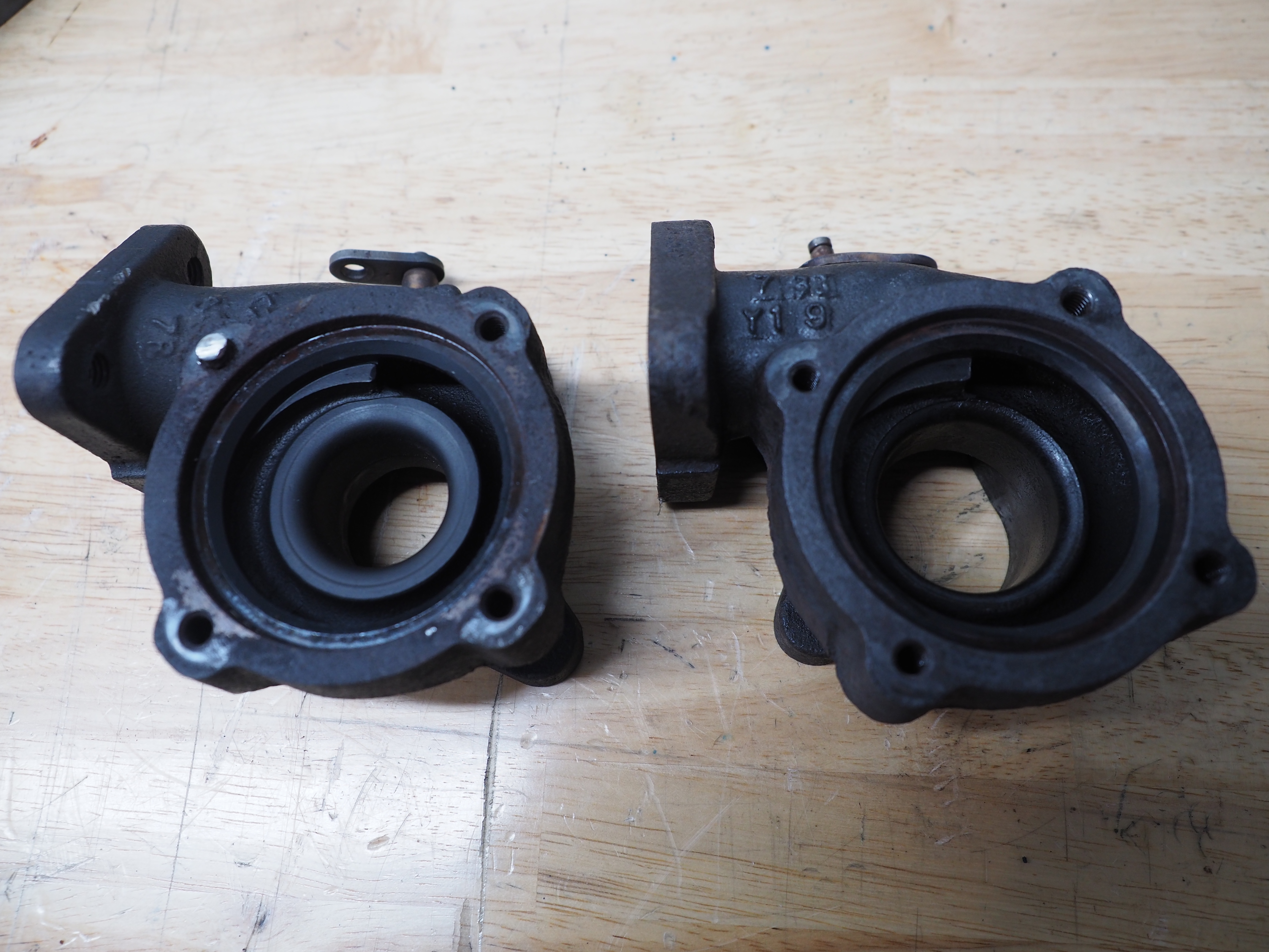
<p><img src="/assets/blog/2022-03-25/JPB11253.JPG" alt="" /></p>

<p>Again, on the left in this picture is the IHI RHB31 VZ24 turbine housing and on the right is the turbine housing for the Hitachi HT07-4A. The CHRA flange dimensions between the two housings are, surprisingly, identical. The HT07-4A is, of course, provisioned for the larger turbine wheel. It is also obviously of a different A/R than the RHB31. This can be seen in the size of the gap visible around the CHRA mounting flange and the size of the scroll visible through this gap.</p>

<p>Inlet and outlet flanges are the same dimensions between the housings.</p>

<h2 id="compressor-housing">Compressor housing</h2>

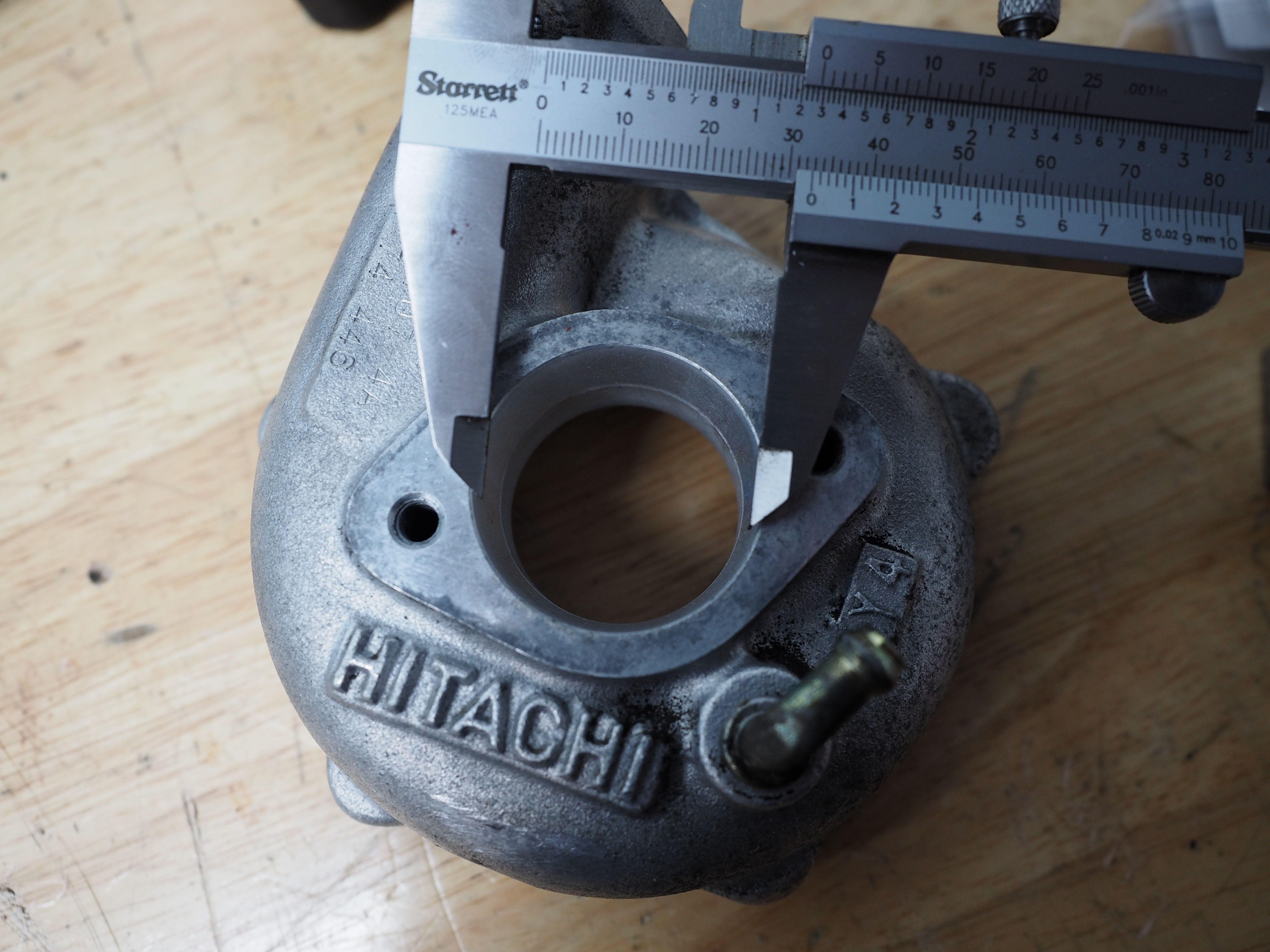
<p>As can be seen in the first picture in this post, the Hitachi HT07-4A compressor housing is much larger in outside diameter than the IHI RHB31 VZ24.</p>

<p>The pictures below shows the EA11R compressor inlet gasket versus the inlet of the RHB31 VZ24 and HT07-4A compressor housings. The same gasket is used on the EA21R Cappuccino, as well.</p>

<p><img src="/assets/blog/2022-03-25/JPB11255.JPG" alt="" />
<img src="/assets/blog/2022-03-25/JPB11256.JPG" alt="" />
<img src="/assets/blog/2022-03-25/JPB11257.JPG" alt="" /></p>

<p>It can be seen that the gasket is a close fit for the RHB31 VZ24, while being smaller in diameter compared to the HT07-4A. It is a paper gasket which can be trimmed to size. The inlet elbow should also be ported to match.</p>

<h2 id="conclusion">Conclusion</h2>

<p><a href="/contact">contact us</a> if you are interested in any of our parts or services.</p>]]></content><author><name>Jeffrey P Burdick</name></author><summary type="html"><![CDATA[Comparing the IHI RHB31 and Hitachi HT07-4A]]></summary></entry><entry><title type="html">Suzuki F6A Port Development part 1</title><link href="https://www.keisport.us/2022/03/10/SuzukiF6AHeadDev01.html" rel="alternate" type="text/html" title="Suzuki F6A Port Development part 1" /><published>2022-03-10T00:00:00-06:00</published><updated>2022-03-10T00:00:00-06:00</updated><id>https://www.keisport.us/2022/03/10/SuzukiF6AHeadDev01</id><content type="html" xml:base="https://www.keisport.us/2022/03/10/SuzukiF6AHeadDev01.html"><![CDATA[<h2 id="introduction">Introduction</h2>

<p>While the Suzuki Cappuccino is a true sports car, it does so while including a somewhat pedestrian engine. The dual-overhead-cam F6A has some interesting aspects, but the valve seats and valves are rather crude. We’ll talk about their limitations, some improvements, and show some performance comparisons.</p>

<h2 id="the-f6a-dohc-valves-and-seats">The F6A DOHC valves and seats</h2>

<p>While some contemporary engines from Honda and Toyota employed valve seats with three angle cuts, Suzuki opted to involve some of their valve seat geometry into the seat insert itself, and employed only two cuts.</p>

<p>Suzuki also uses a very wide 45 degree section on the valve, with a shallow back angle.</p>

<p>To show improvements the cylinder head was tested on an <a href="https://en.wikipedia.org/wiki/Air_flow_bench">air flow bench</a>.</p>

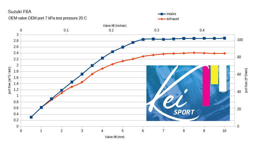
<p><img src="/assets/blog/2022-03-10/oemPort.png" alt="" /></p>

<p>This flow bench chart shows valve lift on the horizontal axis and port flow on the vertical axis. Flow maximum is reached around 6.5 mm of valve lift, which is also the maximum valve lift with the OEM camshafts.</p>

<h2 id="improvements">Improvements</h2>

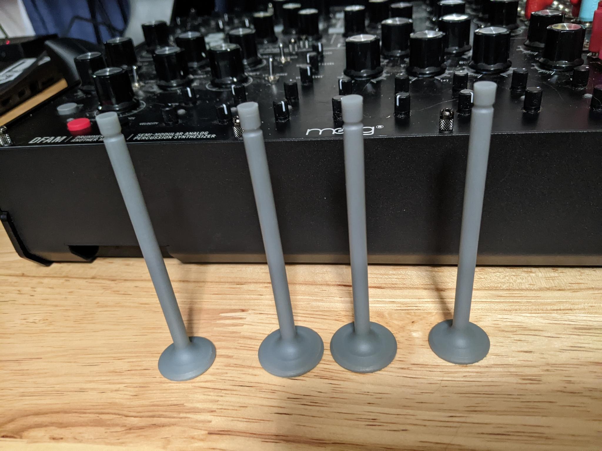
<p>Valves were 3D printed to be able to test different geometries on the flow bench.</p>

<p><img src="/assets/blog/2022-03-10/printedValves.jpeg" alt="" /></p>

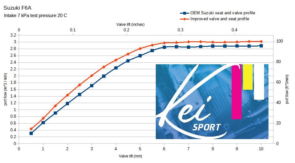
<p>Valve seats were cut with a top, 45 degree, and bottom cut.</p>

<p><img src="/assets/blog/2022-03-10/improvedPort.jpg" alt="" /></p>

<p>This shows that basic improvements can provide measureable gains.</p>

<h2 id="next-steps">Next steps</h2>

<p>Some basic bowl work and core-shift correction is next.</p>

<h2 id="conclusion">Conclusion</h2>

<p><a href="/contact">contact us</a> if you are interested in having us build an F6A, K6A, or E07A cylinder head for you.</p>]]></content><author><name>Jeffrey P Burdick</name></author><summary type="html"><![CDATA[An examination of the OEM Suzuki cylinder head]]></summary></entry><entry><title type="html">EA11R PNP production</title><link href="https://www.keisport.us/2021/07/18/EA11R-PNP-production.html" rel="alternate" type="text/html" title="EA11R PNP production" /><published>2021-07-18T00:00:00-05:00</published><updated>2021-07-18T00:00:00-05:00</updated><id>https://www.keisport.us/2021/07/18/EA11R-PNP-production</id><content type="html" xml:base="https://www.keisport.us/2021/07/18/EA11R-PNP-production.html"><![CDATA[<h2 id="introduction">Introduction</h2>

<p>We have finished development of our PNP ECU for the EA11R <a href="https://en.wikipedia.org/wiki/Suzuki_Cappuccino">Suzuki Cappuccino</a> and are now beginning production. The basic functioning of our PNP was covered in <a href="/2021/01/01/EA11R-PNP.html">our previous blog post</a> and in the <a href="/pnp">PNP documentation page</a>. In this post we’ll discuss some new features and options for our PNP and the tune we’re providing with it.</p>

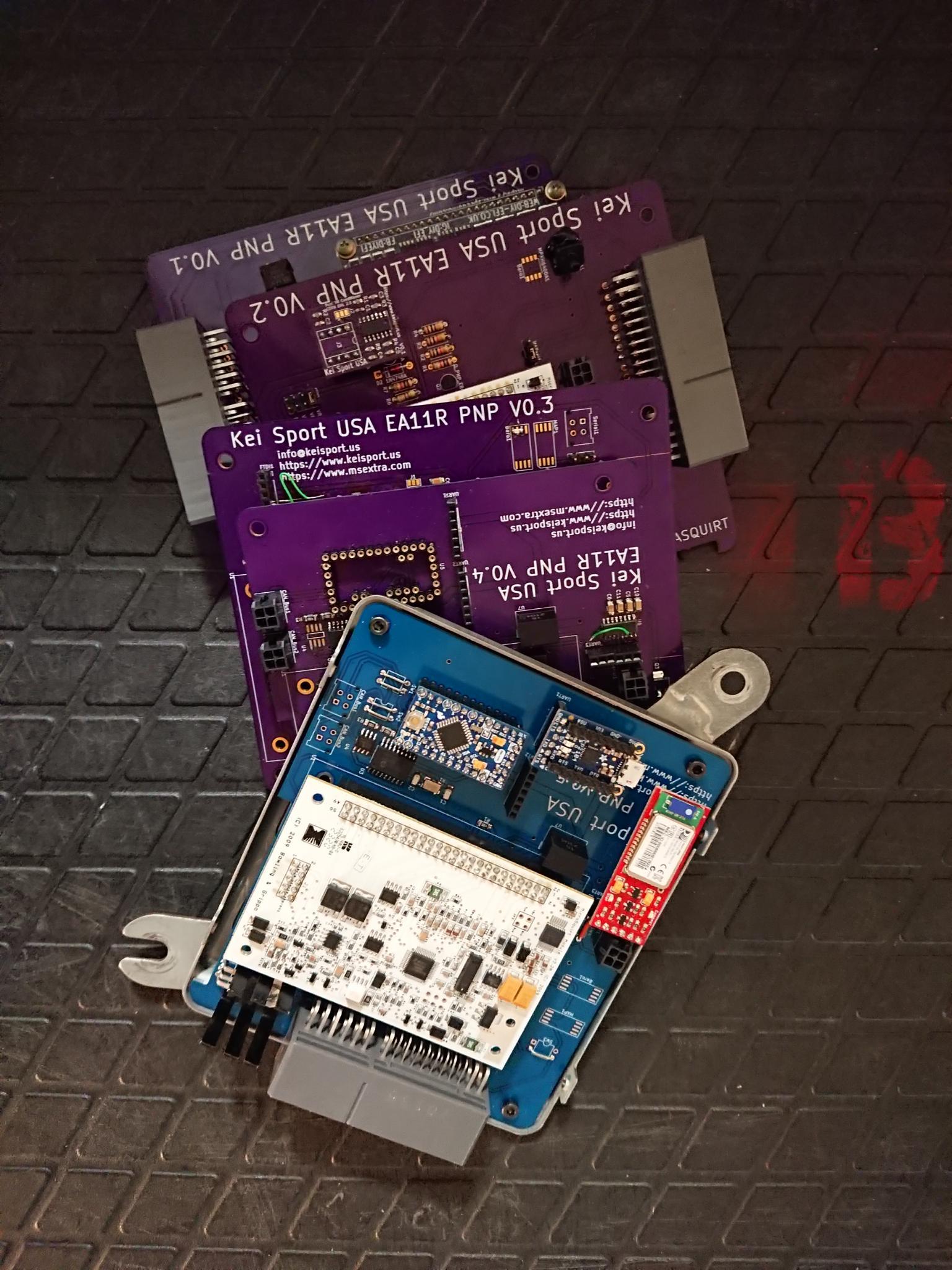
<p><img src="/assets/blog/2021-07-19/pnpFamilyTree.jpeg" alt="" /></p>

<h2 id="tune">Tune</h2>

<p>The main goal of this PNP has been to compete with N1 and N2 ECUs previosly sold by Suzuki/Monster Sport. A considerable amount of work has gone into developing a tune for the PNP to be able to provide the same level of drivability of the OEM Suzuki ECU and increased performance. This is not a “limp to the dyno” tune. It is as complete as we can make it. Many tuning sessions, hundreds of hours of datalogging by beta testers on three continents, hours on a chassis dynomometer, and review by professionals with decades of experience have culminated in a tune which provides out-of-the-box performance.</p>

<p>While we have worked to make as complete of a tune as possible, we have tried to make it easy to work with. Spark and VE tables are split so that table scaling for boost can be done without rescaling or retuning off-boost areas.</p>

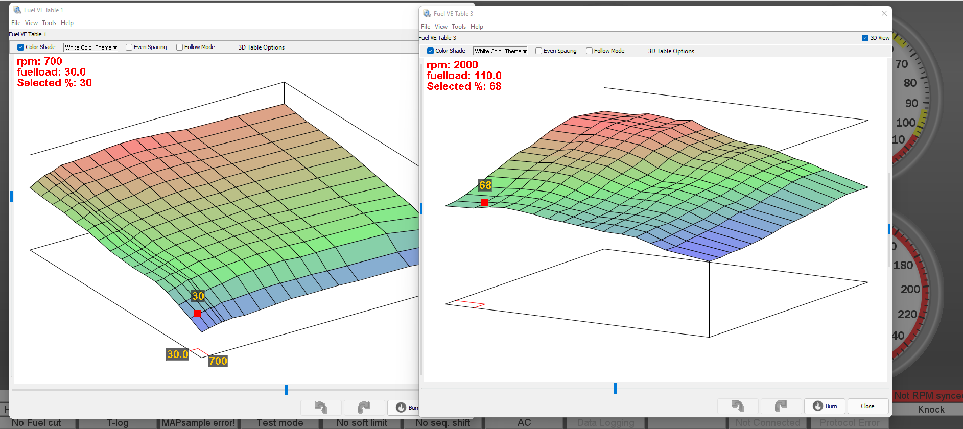
<p><img src="/assets/blog/2021-07-19/tunerStudio-VE.png" alt="" /></p>

<p>We will continue to work with this PNP to provide further tunes for basic modifications like bigger turbos and injectors. Tunes are available in our <a href="https://gitlab.com/burdickjp/ea11r-microsquirt-pnp">gitlab repository</a>.</p>

<h2 id="features">Features</h2>

<p>Based on feedback from our beta testers, we’ve implemented some features in our PNP above and beyond features native to the OEM ECU or Microsquirt Module.</p>

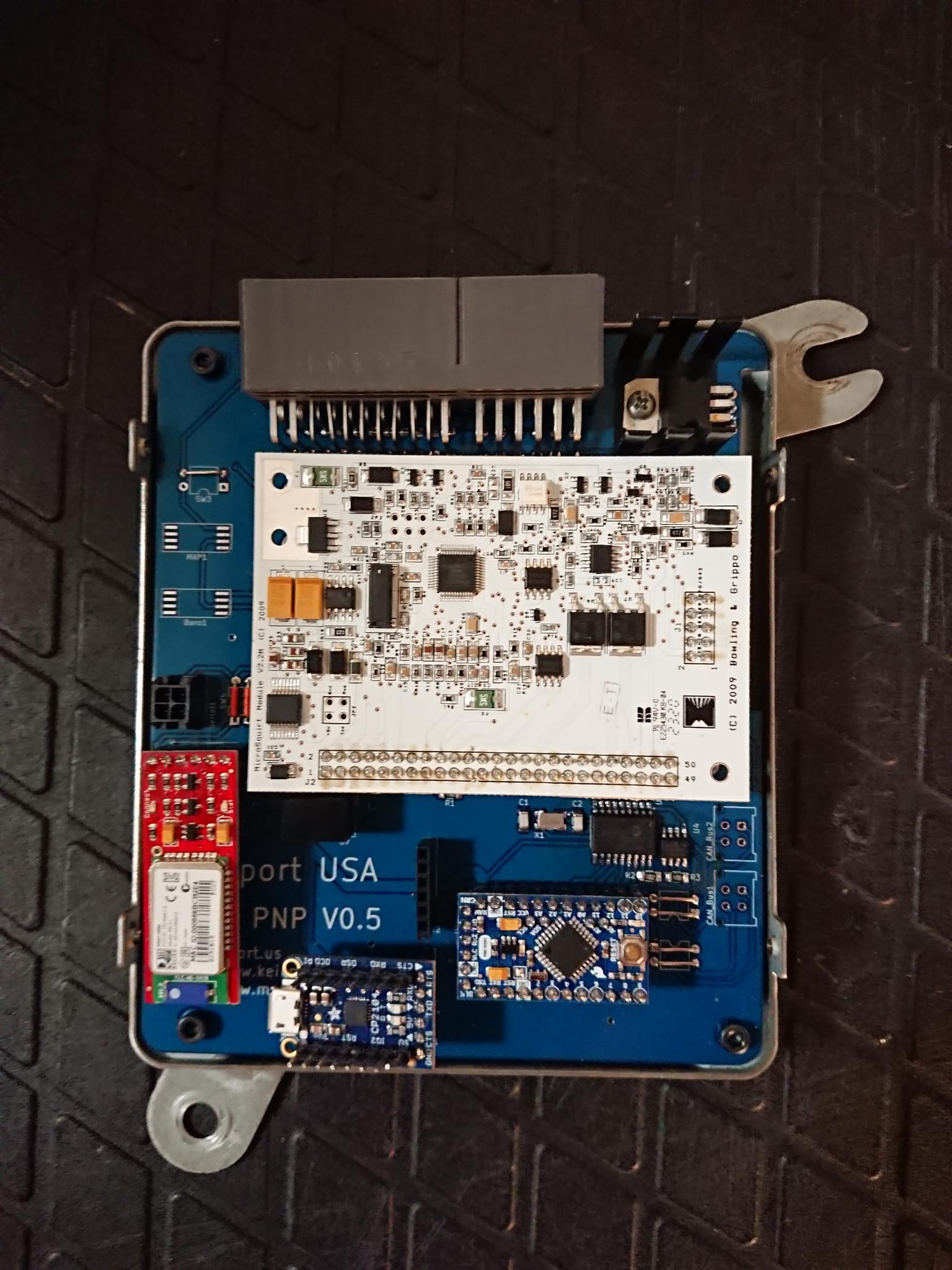
<p><img src="/assets/blog/2021-07-19/pnpv05.jpeg" alt="" /></p>

<h3 id="rs232-and-uart">RS232 and UART</h3>

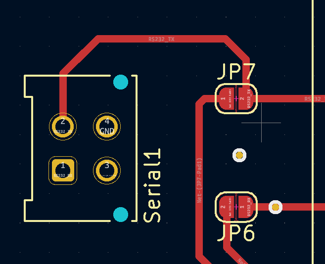
<p>The <a href="https://www.microsquirtmodule.com/">Microsquirt Module</a> is programmed using <a href="https://en.wikipedia.org/wiki/RS-232">RS-232</a>. While this is a reliable and robust protocol, and is still extremely common in industry, it is not common for most consumers. To be able to adapt <a href="https://www.adafruit.com/product/3309">commercially available modules</a> we have included circuitry to convert this RS-232 to TTL-level UART. A jumper allows the user to choose between the RS-232 connector or UART header.</p>

<h3 id="bluetooth-and-usb">Bluetooth and USB</h3>

<p>To provide <a href="/pnp/tune">tuning</a>, <a href="/pnp/datalog">logging</a>, and monitoring we have provided a <a href="https://en.wikipedia.org/wiki/Universal_asynchronous_receiver-transmitter">UART header</a>. This can be used to provide <a href="https://en.wikipedia.org/wiki/USB">USB</a> or <a href="https://en.wikipedia.org/wiki/Bluetooth">bluetooth</a> connctions to the Microsquirt Module. Bluetooth can operate through the ECU case, allowing the PNP to be tuned without any wires going through the case.</p>

<h3 id="can-bus">CAN Bus</h3>

<p>The Microsquirt Module includes the ability to communicate over <a href="https://en.wikipedia.org/wiki/CAN_bus">CAN Bus</a>. Our PNP provides access to the CAN Bus via a 4-pin Molex connector on the PCB and an included DB9 cable. This allows access to the CAN Bus data for dataloggers, dashboards, and external controllers.</p>

<h3 id="arduino">Arduino</h3>

<p>We have included a header on our PNP to fit an <a href="https://www.arduino.cc/en/pmwiki.php?n=Main/ArduinoBoardProMini">Arduino Pro Mini</a> or a <a href="https://www.sparkfun.com/products/14483">SparkFun AST-CAN485</a>. This is connected to the CAN Bus to allow logging or controlling. Two UART connections to the Arduino are provided to allow connection of various devices including USB, Bluetooth, and the <a href="https://www.sparkfun.com/products/13955">SparkFun OpenLog</a>. If the SparkFun AST-CAN485 is used, a second CAN Bus is available on a second 4-pin Molex connector.</p>

<h2 id="conclusion">Conclusion</h2>

<p>We hope that we’ve put together a product which provides the flexibility of a programmable engine management system and performs out-of-the-box as well as the Suzuki Sport ECUs.</p>

<p><a href="/contact">contact us</a> if you have any questions or are interested in a PNP system for your EA11R.</p>]]></content><author><name>Jeffrey P Burdick</name></author><summary type="html"><![CDATA[An introduction of our EA11R Plug-and-Play stand alone engine management system.]]></summary></entry><entry><title type="html">EA11R PNP</title><link href="https://www.keisport.us/2021/01/01/EA11R-PNP.html" rel="alternate" type="text/html" title="EA11R PNP" /><published>2021-01-01T00:00:00-06:00</published><updated>2021-01-01T00:00:00-06:00</updated><id>https://www.keisport.us/2021/01/01/EA11R-PNP</id><content type="html" xml:base="https://www.keisport.us/2021/01/01/EA11R-PNP.html"><![CDATA[<h2 id="introduction">Introduction</h2>

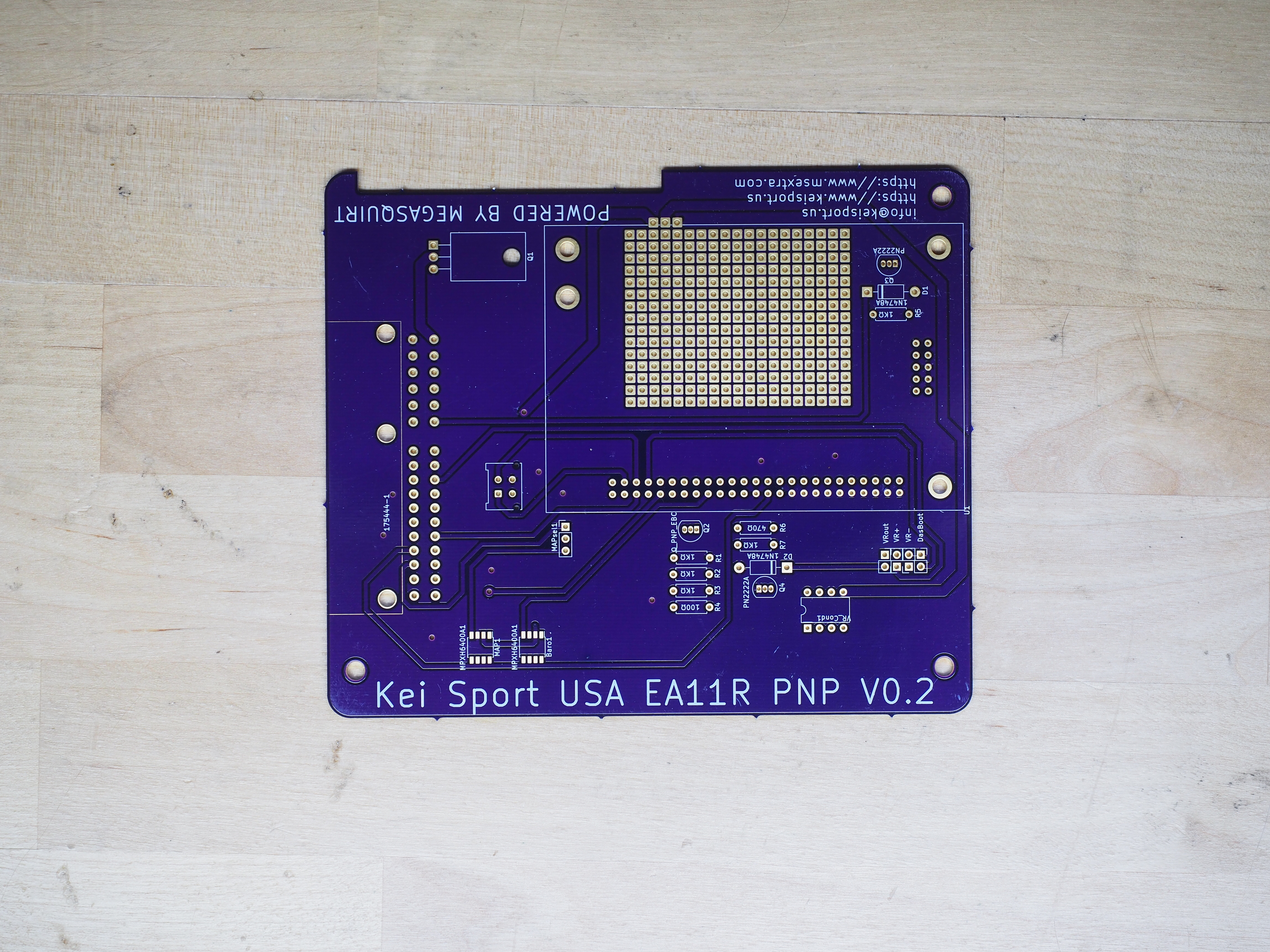
<p>While the Cappuccino is capable and fun in its stock form, its engine management system is archaic. For a long time the only option for those desiring more were modified OEM ECUs developed when the car was new. These are getting harder to find and are unacceptably expensive. To fill this need we are developing a plug-and-play programmable engine management system and providing tunes for the EA11R.</p>

<h2 id="the-plug-and-play">The Plug-and-Play</h2>

<p>Our plug-and-play engine management system installs a Microsquirt Module inside an EA11R Cappuccino ECU case, plugs into the electrical harness, and runs the engine as well as the OEM ECU. This provides datalogging and full tuning capabilities. To facilitate logging and tuning the kit also provides a wideband lambda controller.</p>

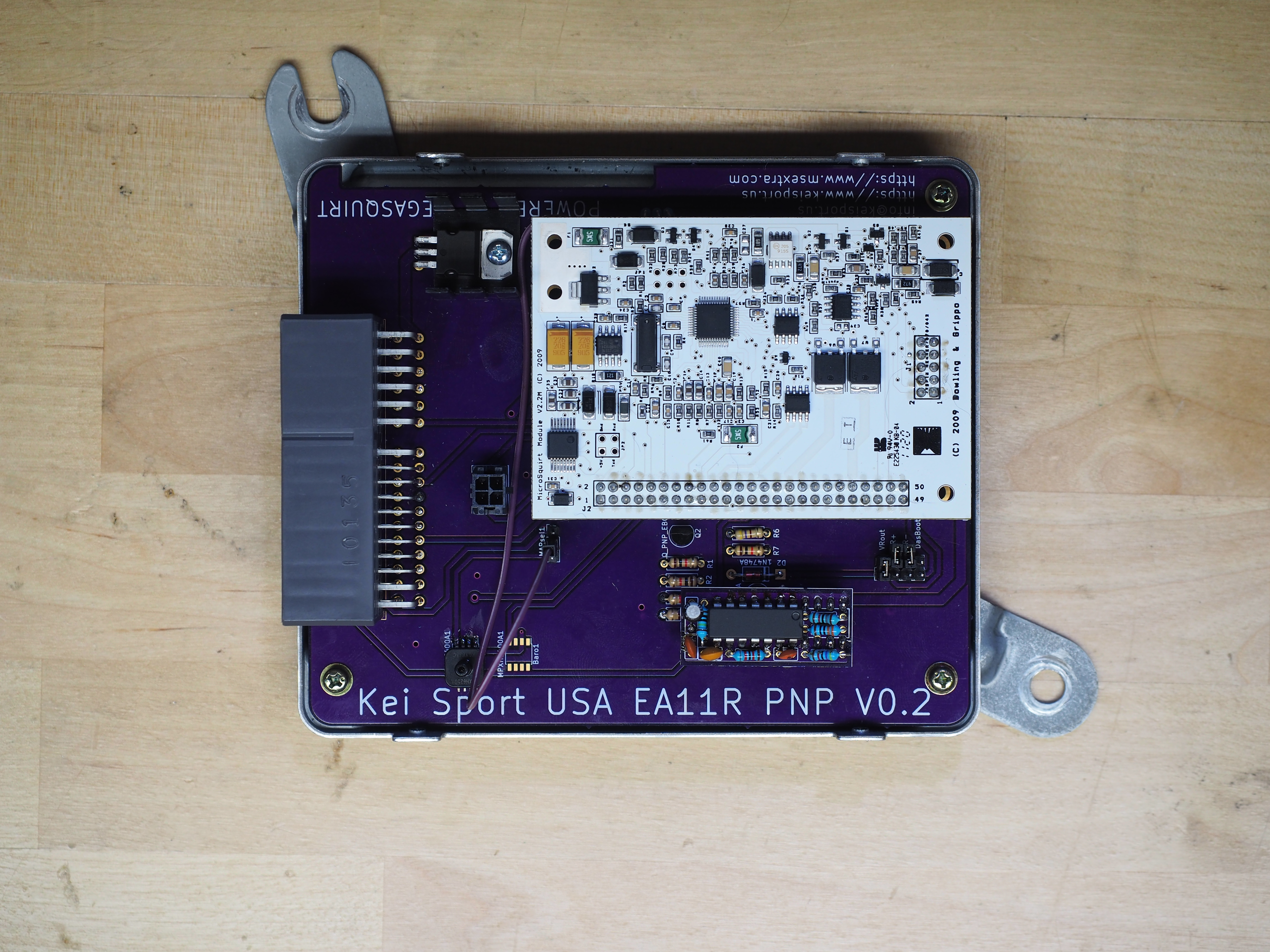
<p><img src="/assets/blog/2021-01-01/JPB10006.JPG" alt="" /></p>

<p>The above picture shows one of our beta prototype PNPs. Some circuits will be different on the production PNP.</p>

<h3 id="the-microsquirt-module">The Microsquirt Module</h3>

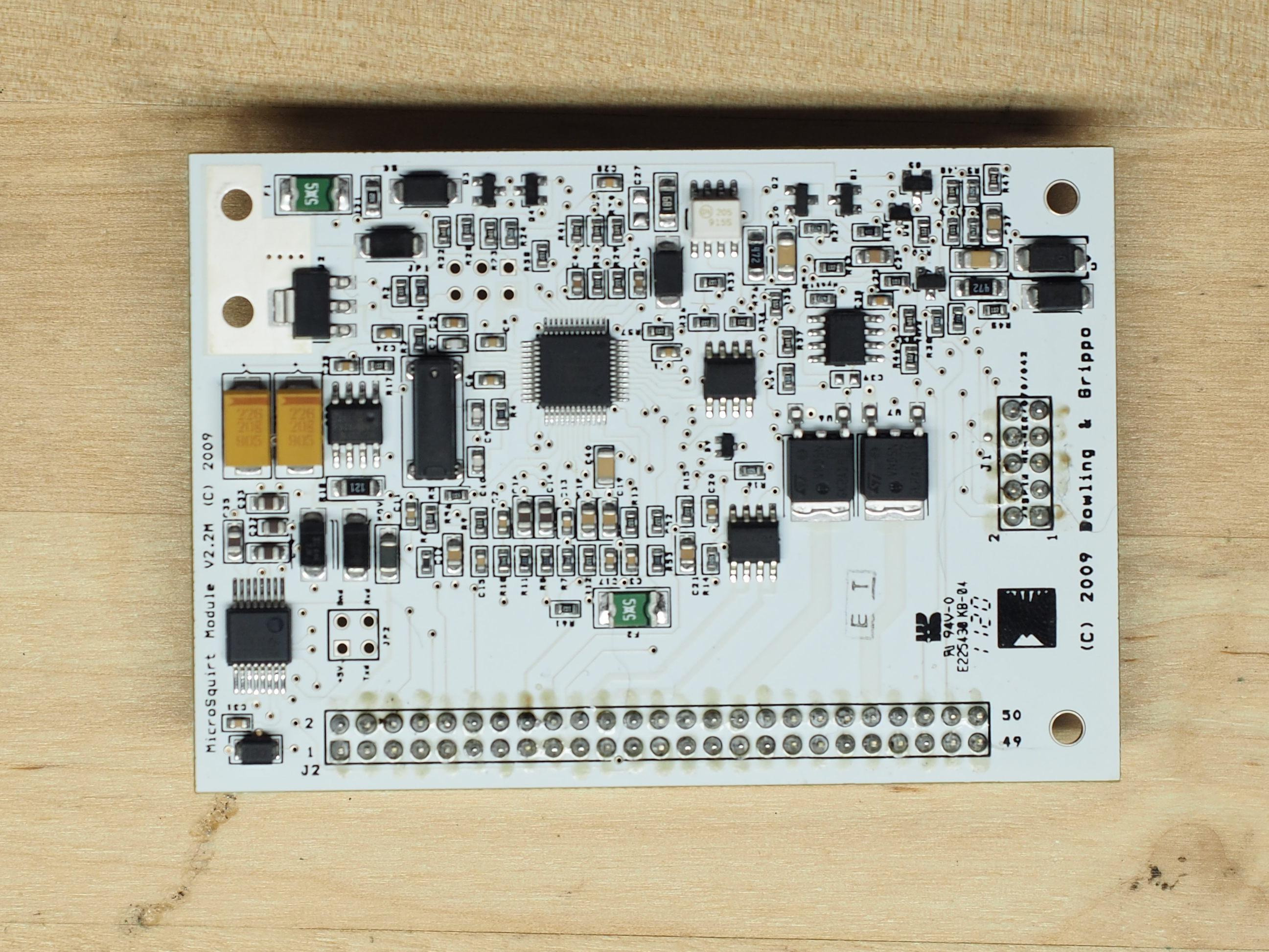
<p>The <a href="https://www.microsquirtmodule.com/index.htm">Microsquirt Module</a> is a programmable engine management system on a small printed circuit board. It is a modular version of the <a href="https://www.msextra.com/product-range/microsquirt/">Microsquirt EFI controller</a> intended for integration into bespoke EFI systems. The Microsquirt Module found success as the basis of <a href="https://www.diyautotune.com/">DIYAutoTune</a>’s <a href="https://www.megasquirtpnp.com/index.php">MSPNP</a> and <a href="https://www.diyautotune.com/support/tech/hardware/diypnp/">DIYPNP</a> systems. In fact, the alpha version of our Plug-and-Play was based on a DIYAutoTune DIYPNP.</p>

<p><img src="/assets/blog/2021-01-01/JPB10001_v1.JPG" alt="" /></p>

<p>For this PNP we are running <a href="https://www.msextra.com/manuals/ms2manuals/">MS2/Extra firmware</a>.</p>

<h3 id="plug-and-play">Plug-and-Play</h3>

<p>To adapt the Microsquirt Module to the EA11R chassis, we’ve developed a PCB which fits inside the OEM EA11R ECU case. This PCB connects to the Cappuccino’s engine harness, and adapts the inputs and outputs between the stock EFI components and the Microsquirt Module.</p>

<p><img src="/assets/blog/2021-01-01/JPB10009.JPG" alt="" /></p>

<p>The video below shows a bench test of the throttle switch to TPS circuitry. This allows the stock Cappuccino’s throttle switches to be interpreted by the microsquirt. Functions such as acceleration enrichment, flood clearing, and idle control rely on this circuitry.</p>

<video width="740" controls="" autoplay="" muted="" loop="">
  <source src="/assets/blog/2021-01-01/MOV_0013.mp4" type="video/mp4" />
</video>

<p>We’ve tried our hardest to make installation as straightfoward as possible. The OEM ECU is removed from the Cappuccino. Its PCB is removed from the case. The PNP PCB is installed in the Cappuccino ECU case. The ECU is then reinstalled in the Cappuccino. Finally, timing is adjusted with a timing light. If logging and tuning will be required the OEM oxygen sensor is replaced with the wideband lambda controller detailed below.</p>

<h3 id="wideband-lambda-controller">Wideband Lambda Controller</h3>

<p>To facilitate logging, tuning, and monitoring we’ve developed a plug-and-play wideband lambda controller. This is based on <a href="https://www.14point7.com/products/spartan-lambda-controller-2">14point7’s Spartan Lambda Controller 2</a> using a genuinge <a href="https://www.bosch-motorsport.com/content/downloads/Raceparts/en-GB/51865867208058251.html">Bosch Lambda Sensor LSU 4.9</a>. It is installed in the down pipe and plugs into the engine harness in place of the OEM Cappuccino oxygen sensor. This lambda system sends the wideband oxygen signal through the OEM Cappuccino electrical harness to the Microsquirt Module.</p>

<h2 id="tuning">Tuning</h2>

<p>This PNP can be tuned using <a href="https://www.tunerstudio.com/index.php/products/tuner-studio">EFI Analytics TunerStudio</a>. This allows tuning all aspects of the engine management system.</p>

<p>We are developing tunes for stock EA11R EFI hardware. This will allow users to maximize the performance of the stock turbocharger and injectors. This tune will be included with production hardware. Further tunes will be developed for popular injector and turbocharger combuinations with the goal of taking performance as far as possible within the capabilities of a plug-and-play system.</p>

<h2 id="whats-next">What’s Next?</h2>

<p>Beta testing is currently ongoing in-house. PNP units will be going out to beta testers shortly. Stay tuned for more updates! We’ll be adding a cornucopia of documentation to the website in support of these as well, so be looking for that!</p>

<h2 id="conclusion">Conclusion</h2>

<p>We hope that we’ve put together a product which provides the flexibility of a programmable engine management system and performs out-of-the-box as well as the Suzuki Sport ECUs.</p>

<p><a href="/contact">contact us</a> if you have any questions or are interested in a PNP system for your EA11R.</p>]]></content><author><name>Jeffrey P Burdick</name></author><summary type="html"><![CDATA[An introduction of our EA11R Plug-and-Play stand alone engine management system.]]></summary></entry><entry><title type="html">Bearing wear in an F6A</title><link href="https://www.keisport.us/2020/06/13/F6AbearingWear.html" rel="alternate" type="text/html" title="Bearing wear in an F6A" /><published>2020-06-13T00:00:00-05:00</published><updated>2020-06-13T00:00:00-05:00</updated><id>https://www.keisport.us/2020/06/13/F6AbearingWear</id><content type="html" xml:base="https://www.keisport.us/2020/06/13/F6AbearingWear.html"><![CDATA[<h2 id="introduction">Introduction</h2>

<p>The Suzuki F6A is a high-reving three cylinder engine with 4 main bearings. This article investigates the bearing system, oiling distribution through the rotating assembly and wear on a set of bearings removed from a used F6A.</p>

<h2 id="the-bearing-system">The Bearing System</h2>

<p>The F6A crankshaft has three crank throws and four main bearings. The mains are numbered 1 through 4 from the timing end of the engine to the flywheel end of the engine.</p>

<p>As is common for Japanese engines from this time period, main bearings are nominally 2 mm thick and rod bearings are nominally 1.5 mm thick. For both bearing types the top and bottom shell are identical. Mains, therefore, have 360 degree oiling.</p>

<p>The OEM bearings are manufactured by <a href="http://www.taihonet.co.jp">Taiho</a>. They are of a bimetal construction, steel backing with an aluminum alloy face. According to <a href="https://www.enginebuildermag.com/2012/10/getting-your-bearings/">this article from Engine Builder Magazine</a> the popularity of bimetal bearings in OEM applications has to do with its long service life for light load applications, but is not ideal for heavy loads.</p>

<p>The F6A has a single pair of thrust bearings mounted on the block side of the #3 main. It is more ideal to have a 360 degree thrust bearing configuration, such as the <a href="https://en.wikipedia.org/wiki/Toyota_A_engine#4A-GE_(16-valve)">Toyota 4A-G</a> has. Even so, Engines such as the <a href="https://en.wikipedia.org/wiki/Mazda_B_engine#BP">Mazda BP</a> have proven to be reliable with a similar 180 degree configuration.</p>

<h2 id="the-oiling-system">The Oiling System</h2>

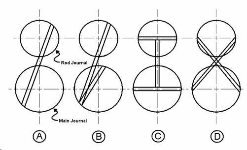
<p>To provide oiling, the F6A has passages drilled through the crankshaft from the mains to the crankpins. These are manufactured as individual holes from a main to a crankpin. This style is shown as <code class="language-plaintext highlighter-rouge">A</code> in the figure below. This figure was originally published <a href="http://www.club4ag.com/faq_and_tech_pages/4A-GE%20Crankshaft%20-%20Detailed%20Specifications%20and%20Analysis.html">by Richard white on the club4ag FAQ and tech pages</a>.</p>

<p><img src="/assets/blog/2020-06-13/image006.jpg" alt="" /></p>

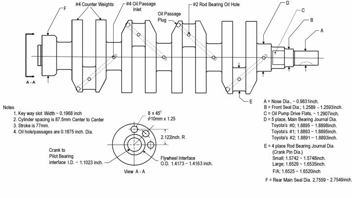
<p>High-performance engines, such as the before-mentioned 4A-G or the venerable <a href="https://en.wikipedia.org/wiki/Suzuki_Hayabusa">Suzuki Hayabusa engine</a>, have cross drinlled crankshafts, like <code class="language-plaintext highlighter-rouge">C</code> in the above figure. A cross-drilled 4A-G crankshaft is shown in the figure below.</p>

<p><img src="/assets/blog/2020-06-13/image004.jpg" alt="" /></p>

<h2 id="balance">Balance</h2>

<p>Like all inline three cylinder four stroke engines, the F6A has some balancing issues. In the case of the F6A these difficulties create some interesting symptoms for the engine bearings.</p>

<p>To help counteract these balance issues the F6A crankshaft has 4 counter weights, around crankpins 1 and 3. They’re 180 degrees out of phase from each other, and 90 degrees out of phase with the second crankpin.</p>

<h2 id="worn-bearings">Worn bearings</h2>

<p><img src="/assets/blog/2020-06-13/JPB10065.JPG" alt="" /></p>

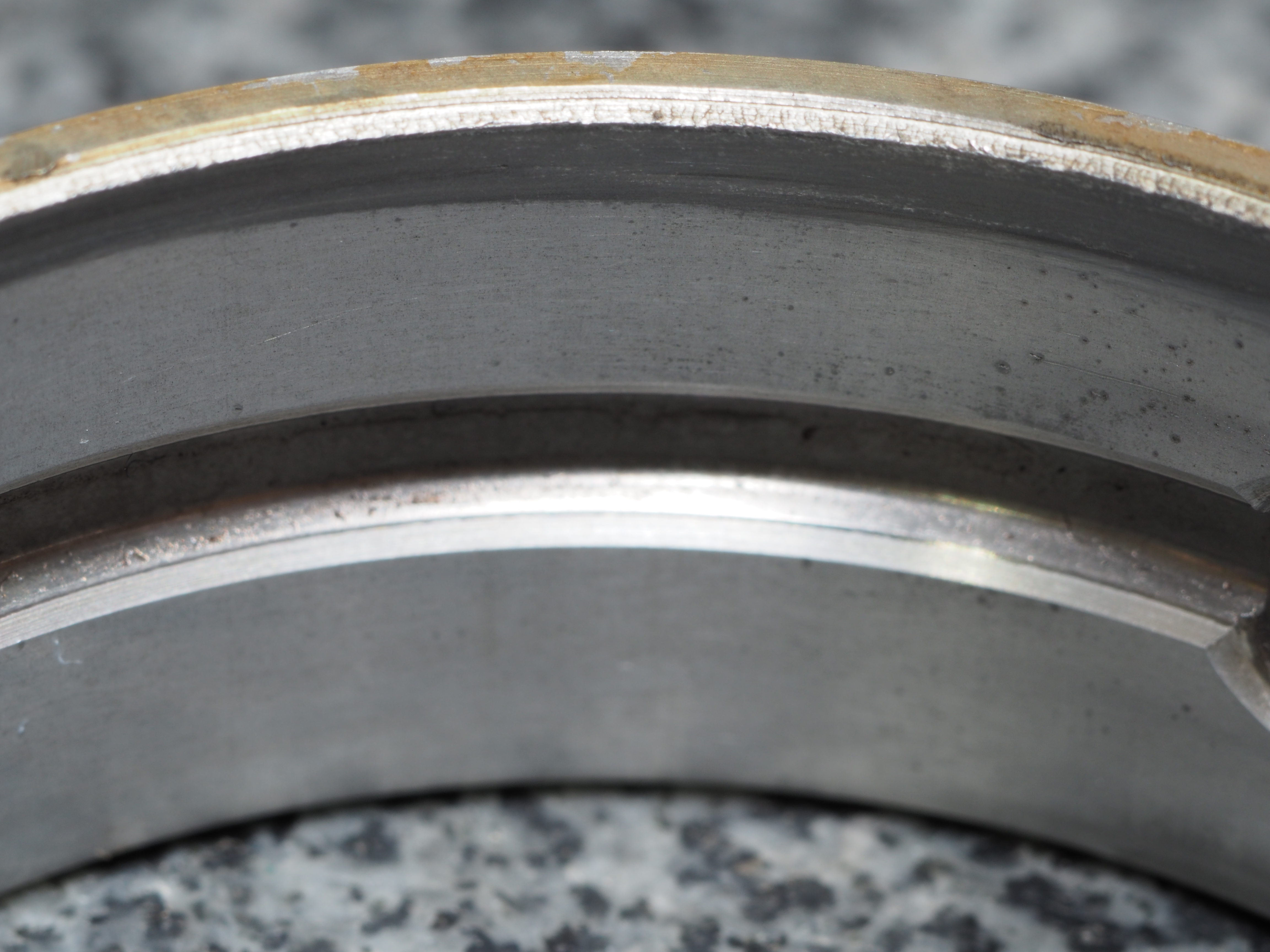
<p>The above picture shows a main bearing shell removed from an F6A from an EA11R. This bearing shows some interesting signs of wear. The main body of the bearing shows some embedded particles. An advantage of aluminum bearings, as discussed in the Engine Builder Magazine cited earlier, is the ability to embed particles, minimizing their effect on the bearing’s performance. This isn’t unusual for a high-mileage bimetal bearing.</p>

<p>What is unusual is the heavily-worn edge of the bearing. Mains number one and four showed this wear on both bearing shells. The wear pattern was toward the timing belt side for the first main and toward the flywheel side for the fourth main. The wear is equal in width around the entire circumfrence of the bearing. The crankshaft showed taper matching the wear on the bearings. This shows that the crankshaft was precessing around its axis of rotation, an effect of the inherent imbalance in the engine.</p>

<h3 id="mitigation">Mitigation</h3>

<p><a href="http://www.power-llc.jp/product/engine/metal.html">Power LLC sells coated trimetal bearings</a> in discrete size ranges, which is advantageous for producing consistent and precise bearing clearances. Power LLC bearings are based on Daido parts. Unfortunately, main bearings are currently discontinued due to a lack of available parts from Daido.</p>

<h2 id="conclusion">Conclusion</h2>

<p>The Suzuki F6A has some interesting challenges when it comes to the reliability of the rotating assembly. Building power is the product of many decisions balancing performance, reliability, delivery, and cost. Decades of performance have shown that these challenges don’t preclude the F6A from producing power.</p>]]></content><author><name>Jeffrey P Burdick</name></author><summary type="html"><![CDATA[Engine bearings from a DOHC Suzuki F6A are examined.]]></summary></entry><entry><title type="html">Determining the rocker ratio of the DOHC Suzuki F6A valvetrain</title><link href="https://www.keisport.us/2020/04/05/F6ArockerRatio.html" rel="alternate" type="text/html" title="Determining the rocker ratio of the DOHC Suzuki F6A valvetrain" /><published>2020-04-05T00:00:00-05:00</published><updated>2020-04-05T00:00:00-05:00</updated><id>https://www.keisport.us/2020/04/05/F6ArockerRatio</id><content type="html" xml:base="https://www.keisport.us/2020/04/05/F6ArockerRatio.html"><![CDATA[<h1 id="introduction">Introduction</h1>

<p>The cylinder head of the Suzuki F6A engine uses a forged steel rocker arm to transfer motion from the camshafts to the valves. The overall valve motion is, therefore, determined by the cam profile and the rocker ratio.</p>

<p>In order to fully understand the valve lift profile the rocker behavior must be understood.</p>

<h1 id="the-valve-rocker-behavior">The valve rocker behavior</h1>

<p>An exploded view of the valvetrain of the DOHC Suzuki F6A is shown below.</p>

<p><img src="/assets/blog/2020-04-05/partsPage.png" alt="" /></p>

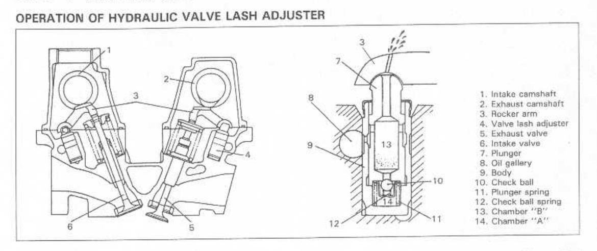
<p>The rocker pivots on a hydraulic lash adjuster with an 8 mm spherical end. The rocker is acted on by the camshaft. The camshaft and valve both contact a radiused surface on the rocker. The rocker-to-valve radius is 12 mm. The camshaft-to-rocker surface is too large for my radius gages.</p>

<p>A cross-section of the valvetrain and lash adjuster is shown below.</p>

<p><img src="/assets/blog/2020-04-05/manualPage.jpg" alt="" /></p>

<p>Worth noting, and verified with measurements using gage pins, is that the valve and lash adjuster sit in parallel bores in the cylinder head. This means that the rocker motion can be easily measured on a surface plate without complicated fixtures, angles, indicators, etc.
Also worth noting is that when the valve is closed the valve tip and lash adjuster are relatively parallel in height along their respective bores.</p>

<h1 id="measurement-setup">Measurement setup</h1>

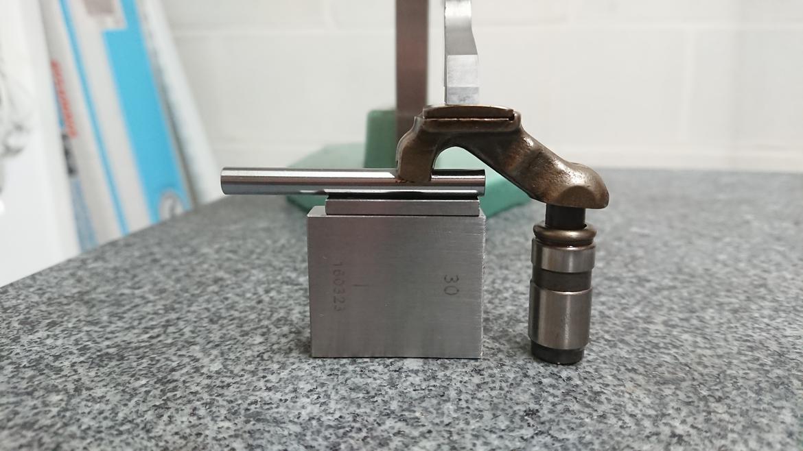
<p>Below is my measurement setup. On the right is a lash adjuster. On the left is a stack of gage blocks. My gage blocks are wider than the acting surface of the rocker, so I am using a 5.5 mm gage pin. The rocker has a radiused surface to act on the valves, so this setup has a point contact between the rocker and the gage pin.</p>

<p>The lash adjuster has a spherical contact, so this setup will pivot around rather loosely until the height gage is brought down on top of the rocker, constraining it from tipping back and forth.</p>

<p><img src="/assets/blog/2020-04-05/surfacePlateSetup.jpg" alt="" /></p>

<p>The nature of contact between the pieces of our measurement setup means that the position or orientation of parts on the surface plate has no bearing on the measured height. The interface between the height gage and rocker is a line contact. As the height gage is lowered and the aforementioned rocking is constrained that line contact becomes horizontal. This can exist anywhere on the plane of the height gage measurement surface.</p>

<h1 id="the-procedure">The procedure</h1>

<p>The gage block stack on the left was stepped in height by one millimeter increments. The height gage was read and recorded for each step.</p>

<h1 id="the-results">The results</h1>

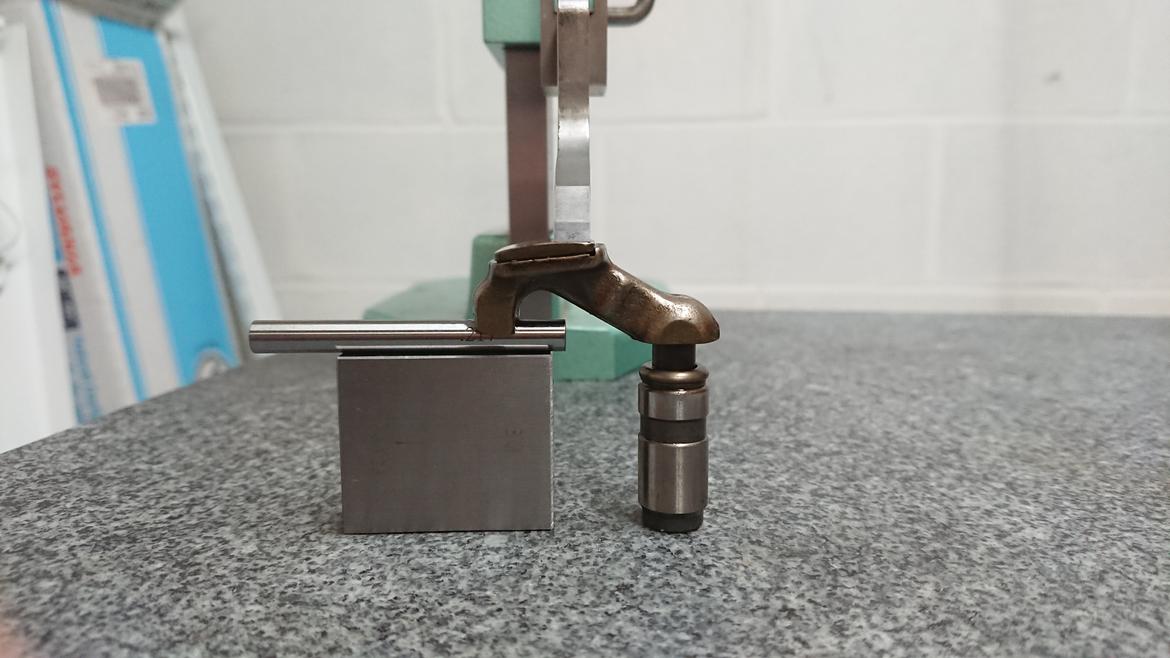
<p>It can be seen in the picture above that the height of the gage blocks puts the point of contact between the rocker and the height gage roughly in the middle of the pad. As the gage block stack height is decreased, the point of contact moves to the right on the pad. This ultimately reaches the right limit of the pad. This represents maximum valve lift. This is shown in the image below. As the gage block stack height is increased the point of contact moves to the left. This represents the minimum valve lift.</p>

<p><img src="/assets/blog/2020-04-05/maxLift.jpg" alt="" /></p>

<p>At minimum lift the rocker ratio is roughly 1:1. At maximum lift it’s nearly 2:1. The camshaft has a 26 mm base circle and 30 mm nose-to-heal. That’s about 4 mm of cam lift, which seems tiny, but with a 2:1 rocker ratio that is about 8 mm, which is more respectable!</p>

<h1 id="exploiting-cam-behavior">Exploiting cam behavior</h1>

<p>Now that we’re equipped with this information, let’s explore what can be done with it.</p>

<h2 id="minimum-base-circle">Minimum base circle</h2>

<p>As shown above, valve lash is taken up by a hydraulic mechanism. The travel of this lash adjuster represents the smallest the base circle of the cam lobe can be. If the cam base circle is too small the rocker will lose contact with the cam lobe at the heel. While that doesn’t seem too bad, when the cam comes back around and contacts the rocker it will be very bad.</p>

<h2 id="maximum-cam-diameter">Maximum cam diameter</h2>

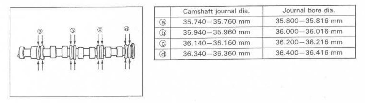
<p>The camshafts are held captive in cam boxes which bolt to the top of the cylinder head. They’re installed from one end and held in by thrust plates. As the camshafts are inserted from one end, the lobes must fit through the bores in the cam boxes.</p>

<p><img src="/assets/blog/2020-04-05/camJournals.jpg" alt="" /></p>

<p>Above shows the camshafts and the journal diameters. As shown, the lobes to the left of journal bore b must fit through b. That bore is nominally 36 mm in diameter. We can have a cam lobe with a nose radius of about 16 mm. If we keep the same base circle diameter we have a nose-to-heel dimension of 31 mm and 10 mm of valve lift. If the base circle can be reduced, even more lift can be had.</p>

<h2 id="ramp-behavior">Ramp behavior</h2>

<p>While ultimate lift is the goal, another characteristic of this valvetrain setup is that the rocker ratio varies as a function of cam lift. This has the advantage of taking a milder grind of the cam lobe, which is easier to accomplish, and resulting in a more aggressive ramp rate. I’m not entirely sure what to do with this specific information, but I am investigating it.</p>

<h1 id="conclusion">Conclusion</h1>

<p>The rocker ratio for the Suzuki F6A is roughly 1:1 when the valve is closed and 2:1 when the valve is fully open. With the measurements provided in the factory service manual, the total valve lift is roughly eight millimeters. With the constraints of the geometry of the head, the ultimately achievable valve lift is roughly 10 mm.</p>

<h2 id="further-work">Further work</h2>

<p>I’ll be measuring the cam lobe profile soon. According to the manual the intake valve opens at 14 degrees before top-dead-center and closes 38 degrees after bottom-dead-center for a total of 232 degrees of duration and the exhaust cam opens 65 degrees before bottom-dead-center and closes 11 degrees after top-dead-center for 256 degrees of duration.</p>]]></content><author><name>Jeffrey P Burdick</name></author><summary type="html"><![CDATA[A rocker arm for a Suzuki F6A is measured to determine the rocker ratio.]]></summary></entry></feed>