Determining the rocker ratio of the DOHC Suzuki F6A valvetrain
Introduction
The cylinder head of the Suzuki F6A engine uses a forged steel rocker arm to transfer motion from the camshafts to the valves. The overall valve motion is, therefore, determined by the cam profile and the rocker ratio.
In order to fully understand the valve lift profile the rocker behavior must be understood.
The valve rocker behavior
An exploded view of the valvetrain of the DOHC Suzuki F6A is shown below.

The rocker pivots on a hydraulic lash adjuster with an 8 mm spherical end. The rocker is acted on by the camshaft. The camshaft and valve both contact a radiused surface on the rocker. The rocker-to-valve radius is 12 mm. The camshaft-to-rocker surface is too large for my radius gages.
A cross-section of the valvetrain and lash adjuster is shown below.
Worth noting, and verified with measurements using gage pins, is that the valve and lash adjuster sit in parallel bores in the cylinder head. This means that the rocker motion can be easily measured on a surface plate without complicated fixtures, angles, indicators, etc. Also worth noting is that when the valve is closed the valve tip and lash adjuster are relatively parallel in height along their respective bores.
Measurement setup
Below is my measurement setup. On the right is a lash adjuster. On the left is a stack of gage blocks. My gage blocks are wider than the acting surface of the rocker, so I am using a 5.5 mm gage pin. The rocker has a radiused surface to act on the valves, so this setup has a point contact between the rocker and the gage pin.
The lash adjuster has a spherical contact, so this setup will pivot around rather loosely until the height gage is brought down on top of the rocker, constraining it from tipping back and forth.
The nature of contact between the pieces of our measurement setup means that the position or orientation of parts on the surface plate has no bearing on the measured height. The interface between the height gage and rocker is a line contact. As the height gage is lowered and the aforementioned rocking is constrained that line contact becomes horizontal. This can exist anywhere on the plane of the height gage measurement surface.
The procedure
The gage block stack on the left was stepped in height by one millimeter increments. The height gage was read and recorded for each step.
The results
It can be seen in the picture above that the height of the gage blocks puts the point of contact between the rocker and the height gage roughly in the middle of the pad. As the gage block stack height is decreased, the point of contact moves to the right on the pad. This ultimately reaches the right limit of the pad. This represents maximum valve lift. This is shown in the image below. As the gage block stack height is increased the point of contact moves to the left. This represents the minimum valve lift.
At minimum lift the rocker ratio is roughly 1:1. At maximum lift it’s nearly 2:1. The camshaft has a 26 mm base circle and 30 mm nose-to-heal. That’s about 4 mm of cam lift, which seems tiny, but with a 2:1 rocker ratio that is about 8 mm, which is more respectable!
Exploiting cam behavior
Now that we’re equipped with this information, let’s explore what can be done with it.
Minimum base circle
As shown above, valve lash is taken up by a hydraulic mechanism. The travel of this lash adjuster represents the smallest the base circle of the cam lobe can be. If the cam base circle is too small the rocker will lose contact with the cam lobe at the heel. While that doesn’t seem too bad, when the cam comes back around and contacts the rocker it will be very bad.
Maximum cam diameter
The camshafts are held captive in cam boxes which bolt to the top of the cylinder head. They’re installed from one end and held in by thrust plates. As the camshafts are inserted from one end, the lobes must fit through the bores in the cam boxes.
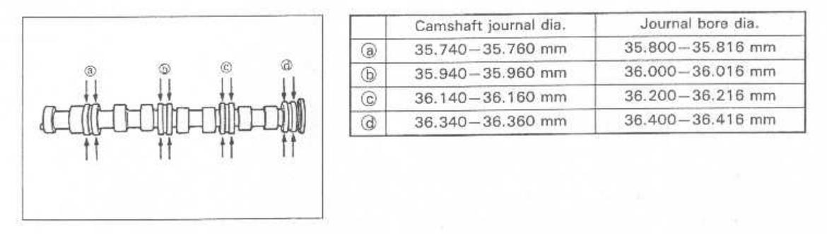
Above shows the camshafts and the journal diameters. As shown, the lobes to the left of journal bore b must fit through b. That bore is nominally 36 mm in diameter. We can have a cam lobe with a nose radius of about 16 mm. If we keep the same base circle diameter we have a nose-to-heel dimension of 31 mm and 10 mm of valve lift. If the base circle can be reduced, even more lift can be had.
Ramp behavior
While ultimate lift is the goal, another characteristic of this valvetrain setup is that the rocker ratio varies as a function of cam lift. This has the advantage of taking a milder grind of the cam lobe, which is easier to accomplish, and resulting in a more aggressive ramp rate. I’m not entirely sure what to do with this specific information, but I am investigating it.
Conclusion
The rocker ratio for the Suzuki F6A is roughly 1:1 when the valve is closed and 2:1 when the valve is fully open. With the measurements provided in the factory service manual, the total valve lift is roughly eight millimeters. With the constraints of the geometry of the head, the ultimately achievable valve lift is roughly 10 mm.
Further work
I’ll be measuring the cam lobe profile soon. According to the manual the intake valve opens at 14 degrees before top-dead-center and closes 38 degrees after bottom-dead-center for a total of 232 degrees of duration and the exhaust cam opens 65 degrees before bottom-dead-center and closes 11 degrees after top-dead-center for 256 degrees of duration.